Digital Moisture Control Thermostat Installation and Operation Manual PNEG – 1711 Date: 2009 PNEG - 1711 Digital Thermostat Owner’s Manual Page 1 of 22 06/30/2009
READ THESE INSTRUCTIONS BEFORE INSTALLATION and OPERATION. SAVE FOR FUTURE REFERENCE. Thank you for choosing a GSI Vision Series grain dryer. These units are among the finest grain dryers ever built; designed to give you excellent operating performance and reliable service for many years. This manual describes the installation and operation for all standard production model dryers.
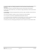
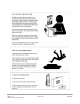
8. Set pressure regulator to avoid excessive gas pressure applied to a burner during ignition and when burner is in operation. See page 19 for operating gas pressures. Do not exceed maximum recommended drying temperatures. 9. Do not operate the dryer if any gas leak is detected. Shut down and repair before further operation. 10. Clean grain is safer and easier to dry. Fine material can be highly combustible, and it also requires removal of extra moisture. 11.
PNEG - 1711 Digital Thermostat Owner’s Manual Page 4 of 22 06/30/2009
PNEG - 1711 Digital Thermostat Owner’s Manual Page 5 of 22 06/30/2009
PNEG - 1711 Digital Thermostat Owner’s Manual Page 6 of 22 06/30/2009
PNEG - 1711 Digital Thermostat Owner’s Manual Page 7 of 22 06/30/2009
Table of Contents TABLE OF FIGURES ........................................................................................................................................................ 9 1. CONTENTS ..............................................................................................................................................................10 2. INSTALLATION...................................................................................................................................
Table of Figures Figure 1 - Drill Pattern ......................................................................................................................................................11 Figure 2 - A1 through A3 Connections...............................................................................................................................12 Figure 3 - B1 through B6 Connections...................................................................................................................
1. Contents 1.1 Digital Thermostat Contents Qty 1 4 4 GSI Part Number D03-0852 S-8570 S-2010 Description Digital Moisture Control Thermostat 2.5” #10-24 Machine Screw, Pan Head Phillip Stainless Steel Nut, Nylock #10-24 Zinc 2. Installation 2.1 Mounting in Control Panel 1. Turn the Main Power Disconnect to the “OFF” position. 2. Use the following table to document the wiring of the Honeywell that is being replaced, as this will be referenced later in the manual.
Figure 1 - Drill Pattern 5. Before mounting the GSI moisture control to the panel door, attach the necessary wiring. Be sure to kill power when installing. Table 1 depicts the relation between the Honeywell controller and the GSI moisture control. Refer to Figure 2 and Figure 3 for connections of the GSI moisture control. For example, if a wire is attached to the connection labeled “1” on the Honeywell controller, that wire would need to be attached to “A1” on the GSI moisture control.
Figure 2 - A1 through A3 Connections Figure 3 - B1 through B6 Connections PNEG - 1711 Digital Thermostat Owner’s Manual Page 12 of 22 06/30/2009
6. Once the control has been wired, refer to Figure 4 for mounting the new controller to the control panel door. The S-7931 nuts are already installed in the bottom assembly (Figure 3). There are recessions on the bottom of the corners of the box that fit the nuts. Make sure to place the gasket between the two box pieces. Figure 4 - Assembly Drawing 7. The GSI Digital Thermostat is now ready for operation. Refer to Section 3 for operation instructions. 3. Operation 3.
3.2 Configuration Menu To access the configuration menu, press and hold the “SET” button until the configuration menu appears, approximately five seconds. Once in the menu structure, us “UP” and “DOWN” to browse through the options and “SET” to enter the sub menu. While in the configuration, if the user allows approximately twenty-five seconds to pass without pressing a button, the configuration menu is exited and no changes will be saved. The following are the menu options. 3.2.
3.3 Operating Modes 3.3.1 Hi / Lo Operation (Plenum Temperature Control) There are three states the burner can assume when Hi / Lo operation is selected: High, Low, and Off. Anytime the sensor temperature is below the temperature setpoint minus the differential, the controller will engage the “High” state. Once the sensor temperature rises above the setpoint plus the temperature differential, the Thermostat will enter “Low” mode and will remain in this state until one of two things happen: 1.
Table 3 - On / Off Controller States Controller State On Off Relay 1 Closed (0 Ω) Open (∞ Ω) Relay 2 Closed (0 Ω) Open (∞ Ω) The default screen displays current state of controller, current sensor temperature, and current setpoint. Figure 6 - Default On / Off Screen 3.3.3 Dryer / TopDry Operation (Grain Temperature / Moisture Control) There are two states the controller can assume using Dryer / TopDry operation: Engaged and Disengaged.
Figure 7 - Engaged Mode, notice the temperature to the left Figure 8 - Disengaged Mode, notice the temperature to the right PNEG - 1711 Digital Thermostat Owner’s Manual Page 17 of 22 06/30/2009
4. Example Setup Once the thermostat has been wired and secured to the control panel door, turn the power on. The display will show “GSI Group, LLC” for approximately ten seconds while the thermostat is booting. The next screen will display “No Operation”, provided this is the first time the controller has been used. 1. Press and hold the “SET” button until the configuration menu appears, approximately five seconds. You can press and release “UP” or “DOWN” to navigate through the menus.
6.
PNEG - 1711 Digital Thermostat Owner’s Manual Page 20 of 22 06/30/2009
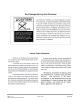
7. Warranty Limited Warranty The GSI Group, LLC. (“GSI”) warrants products which it manufactures to be free of defects in materials and workmanship under normal usage and conditions for a period of 12 months after sale to the original enduser or if a foreign sale, 14 months from arrival at port of discharge, whichever is earlier.
Prior to installation, the end-user has the responsibility to comply with federal, state and local codes which apply to the location and installation of products manufactured or sold by GSI.