CE Compliant Top Dry Series 2000 Autoflow Operators Manual PNEG-1820 Date: 04-10-12 PNEG-1820
PNEG-1820 CE Compliant Top Dry Series 2000 Autoflow
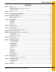
Table of Contents Contents Chapter 1 Safety .....................................................................................................................................................4 Safety Guidelines .................................................................................................................................. 4 Fan/Heater Installation and Operating Instructions ............................................................................... 5 Safety Sign-Off Sheet ..........
1. Safety Safety Guidelines This manual contains information that is important for you, the owner/operator, to know and understand. This information relates to protecting personal safety and preventing equipment problems. It is the responsibility of the owner/operator to inform anyone operating or working in the area of this equipment of these safety guidelines. To help you recognize this information, we use the symbols that are defined below. Please read the manual and pay attention to these sections.
1. Safety Fan/Heater Installation and Operating Instructions Thank you for choosing a Top Dry Series 2000 Autoflow. This manual describes the operation of CE Compliant Top Dry Series 2000 single fan, multi-fan heater control units. Our principal concern is your safety. This manual is written to help you understand safe operating procedures for you and your co-workers.
1. Safety Safety in Maintenance Shut off and lock power and fuel supply to the dryer before entering or carrying out service or maintenance. Before entering the drying bin allow run the fan only for 20 minutes to purge products of combustion and cool and heater components. Ensure the grain chutes are empty by performing a manual dump before entering. Before opening the fuel train safely de-pressurise the system. Access to items at high level will require suitable safe access equipment, such as scaffold.
1. Safety Safety Sign-Off Sheet As a requirement of O.S.H.A., it is necessary for the employer to train the employee in the safe operating and safety procedures for this auger. This sign-off sheet is provided for your convenience and personal record keeping. All unqualified persons are to stay out of the work area at all times. It is strongly recommended that another qualified person who knows the shut down procedure be in the area in the event of an emergency.
2. Decals Safety decals must be read and understood by all people in and around the top dry area. If any safety decals are not displayed on the top dry or if they are damaged, contact the GSI Group, Inc. for replacement: Decals 1004 E. Illinois St. Assumption, IL.
2. Decals High Voltage DC-2163 Background: White Colors: Black, ANSI Yellow and ANSI Blue Size: 3.940" x 1.970" Isolate and lock from power before removing guards or opening enclosure Replace all guards and lock enclosure before reconnecting to power DC-2163 DC-2164 Automatic Machinery Background: White Colors: Black, ANSI Yellow and ANSI Blue Size: 3.940" x 1.
2. Decals Failure to follow these instructions will result in structural damage or collapse Ear protection must be worn in this area NO YES Use CENTRE OUTLET ONLY until NO grain remains above the outlet Side outlets to be used ONLY when this condition is satisfied Lock all side outlets to prevent incorrect use DC-2210 DC-2166 DC-2166 DC-2210 Background: White Colors: Black and ANSI Blue Size: 5.910" x 3.940" Background: White Colors: Black, ANSI Yellow, ANSI Blue and ANSI Red Size: 5.910" x 3.
3. Fuel and Electrical Specifications Top Dry CE Heater Specifications Fuel Specifications Gross CV = 98.37 MJ/m3 LPG Motor Fan Maximum Minimum Maximum Minimum Maximum Minimum Air Air Static Static Heat Heat Maximum Minimum Maximum Orifice Burner Burner Gas I.D. Pressure Pressure Flow kW m3/s m3/s Pa Pa kW kW mBar mBar mm m3/h 36" 11.19 8.74 2.83 747.30 373.65 1311.91 495.30 420.00 16.00 9.74 50.31 40" 11.19 12.75 5.20 747.30 373.65 1786.16 674.19 420.00 16.00 11.
4. Electrical Installation The electrical supply must be capable of the full demand from the dryer, including aeration fan, fill and empty equipment and start currents. All CE Top Dry fans are star delta starting. Refer to electrical specifications Table on Page 11 for minimum current demand per fan heater. For twin fan units, double the minimum demand. Allow for fill and empty equipment loads. Power supply to the dryer must include a suitable, lockable supply disconnect switch (isolator).
5. Fuel Installation Fuel Supply The dryer requires a suitable fuel supply. Refer to fuel specifications Table on Page 11 for fuel flow requirements. Liquid LPG Dryers with internal vaporizers require LPG in liquid form. Vapor LPG Dryers without internal vaporizers require LPG in vapor form. LPG tanks must have adequate vaporizing capacity to supply the maximum fuel flow given in fuel specifications Table on Page 11. Alternatively and external vaporizer may be used.
6. Control Panel Dryer Control Panel Figure 6A Moisture Control Switch Determines if the grain temperature set point is used in the operation of the dryer. When “ON” position, the grain will be dumped when it reaches the temperature set point and the dry timer has reached zero. When “ON” the switch is lit when the grain is below set point. Control Power Switch Turns ON/OFF power to the electronic monitoring control system.
6. Control Panel Load Auger Switch Controls the operation of the drying chamber fill system(s). Switch is lit when the fill system(s) are running. AUTO = Fill system(s) start and stop automatically depending level of grain in drying chamber. When operating in the Autobatch mode the fill system(s) will shut off 2/3 of the way through the dry cycle regardless of drying chamber level. ON = Fill system(s) are ON when the dryer is running. Fan Switch Controls the operation of the main drying fan(s).
7. Control System Electronic Monitoring Control System Figure 7A Electronic Monitoring Control System This controls all timing functions and safety circuits. It provides printed messages and warnings. Turn control power to “ON” to start the control. The control will enter the main drying screen. Setting the Dry, Cool and Unload Timers These set the dry, cool and dump cycle times. The timer settings are displayed above the Timer button. To alter the setting: 1. Press the Dry, Cool or Unload Timer button.
7. Control System Setting the Delays The following timers are set using the same procedure, but the Reset button does not need to be pressed to enter the new values into memory immediately. AUX. 1 DELAY - Not used. REFILL DELAY - Used only on batch units. This delays the start of drying to allow the drying chamber to fill. If the unit does not refill within this time the unit will give a “dry chamber empty” error.
7. Control System Use the Increase and Decrease buttons to select the correct time or date. Press the Enter button to accept. LOW LEVEL TEST MODE - Use the Increase and Decrease buttons to enable or disable Drying Chamber Low Level switch monitoring. WET TANK TEST MODE - Use the Increase and Decrease buttons to enabled or disabled wet supply level switch monitoring. START FANS WITH HIGH - Use the Increase and Decrease buttons to enable or disable fan starting based on the Upper Drying Chamber Level switch.
8. Fill System Control Box Figure 8A The fill system control box houses the motor starters for fill system #1, fill system #2 and the aeration fan. Switches are located on the front of the fill system control box and an Emergency Stop switch is located on the side of the control box.
8.
8. Fill System Control Box Flame Probe, Ignitor and Burner Assemblies Parts List Ref # 1-3 Description Flame Probe Assembly Network 1 Boot 8 mm Silicone 90° 2 Flame Sensor 6" Long Rod 3 Flame Sensor Bracket 4-8 Ignitor Assembly 4 Dual Probe Ignitor Bracket 5 Ignitor Air Deflector Angle 6 Ignitor Half Clamp 7 Ignitor Flame 8 Ignition Wire Assembly (Includes Both Wires) 9 Cone 10 Vaporizer Coil Loosen this bolt to adjust the vaporizer coil.
9. Error Messages and Valve Proving System Error Messages Burner * Loss Flame The flame sensor in burner number * has failed to detect flame. Possible causes: Burner failed to light. 1. Check fuel supply and pressure. 2. Check spark. 3. Check all solenoid valves are opening. Flame sensor needs adjusting. 1. It must be in the flame. 2. It can be bent gently if required. Fan * Vapor High-Limit The LP gas vapor temperature has exceeded 109°C causing the high-limit to open. This will reset when cool.
9. Error Messages and Valve Proving System Drying Chamber Overflow The grain level in the drying chamber has reached the Drying Chamber Overflow Rotary switch. Grain will have to be dumped from the drying chamber to the storage chamber before the unit can be re-started. This error indicates that either the drying chamber High Level Rotary switch is faulty or the time on the load delay or Aux. 1 delay needs to be lowered.
9. Error Messages and Valve Proving System Grain High-Limit The grain temperature in the drying chamber is too high. Valve Proving System The main safety shut-off valve is fitted with a proving system which will prevent burner start-up if the valve is leaky. High-low valve Low-fire adjustment screw Valve proving system High gas pressure switch Figure 9A Check the light status on the VPS. Red light indicates leaky valve. VPS is reset by pressing the Reset button.
10. Initial Start-Up Dryer Commissioning Electrical 1. Carry out earth bonding test per EN60204 and/or local electrical laws and regulations. 2. Check adequate power supply. (Refer to electrical specifications Table on Page 11.) 3. Voltage at phases must be within 5% of rated voltage. 4. Voltage drop must not exceed 5% when under full load. 5. Check overload settings for each motor circuit. 6. Complete full electrical tests in accordance with EU Directives and local laws, regulations and codes.
10. Initial Start-Up Gas Train (Continued) 6. Set burner low-fire pressure. • Set plenum temperature to approx. 10°C above ambient. • Light burners. • On low fire, adjust high-low valve minimum setting to give pressure as per fuel specifications Table on Page 11. 7. Read pressure at burner gauge. (See Figure 9A on Page 24.) 8. Run burners and check burner modulates correctly. 9. Check gas pressure remains stable fill out gas train commissioning check sheet.
11. Pre-Season Checks Before the dryer is filled, inspect the unit and check the operation of the dryer as follows. Never enter a bin where grain is present.
11. Pre-Season Checks Drying Chamber Inspect each dump hopper for obstructions. Make sure that the gap between the discharge flow plates and the floor sheets is a minimum of 38 mm. Rotary Switches Check all rotary switches are spinning freely. Linear Actuator Turn the Dump switch “manual open”. Check the stroke on the actuator is 300 mm to 350 mm. Adjust if necessary. Make sure that all pulleys and cables move freely. With the actuator extended, view each dump chute to make sure they are completely open.
11. Pre-Season Checks Fill System Prepare the wet storage tank to deliver grain to the dryer. Make sure all personnel clear. Switch load auger to “AUTO”. Grain should be delivered from the wet supply tank to the dryer. When the display shows “GRAIN LOW LEVEL YES” close the valve that supplies the fill system(s) with wet grain from the wet supply tank. When the load auger empties turn it “OFF”.
12.
12. Autoflow Theory During the dump cycle 1/3 of the grain is dumped into the storage chamber. After the dump cycle, the unit returns to the beginning of the dry cycle, the fill system(s) refill the drying chamber and the process begins again. The unit continues with the same operation until either no grain is present against the Wet Supply Rotary switch or the storage chamber becomes full. If the wet storage tank becomes empty, the fill #1 and fill #2 delays starts to count down.
13. Start-Up Procedure Initial Dryer Start-Up 1. With Control Power switch OFF, turn ON the main power supply. 2. Pull out all Emergency Stop switches. 3. Set the switches as follows: • Moisture Control switch - “ON” • Aeration Fan switch - “AUTO” • Load Auger switch - “OFF” • Fan switch - “AUTO” • Heater switch - “AUTO” • Dump switch - “AUTO” • Dry and Hold switch - “OFF” 4. Make sure there is wet grain in the wet supply tank. 5. Turn control power “ON” position. 6.
13. Start-Up Procedure 12.
13. Start-Up Procedure Normal Start-Up When the dryer is started with grain in the drying chamber that has already been partially dried, the dryer can be started without making any adjustments to time or temperature; however, the moisture of the grain should be checked after the fourth dump. Last Fill 1. Stop the dryer when all the wet grain has been loaded into the drying chamber and turn OFF the Moisture Control switch. 2.
14. Warranty GSI Group, LLC Limited Warranty The GSI Group, LLC (“GSI”) warrants products which it manufactures to be free of defects in materials and workmanship under normal usage and conditions for a period of 12 months after sale to the original end-user or if a foreign sale, 14 months from arrival at port of discharge, whichever is earlier.
This equipment shall be installed in accordance with the current installation codes and applicable regulations, which should be carefully followed in all cases. Authorities having jurisdiction should be consulted before installations are made. GSI Group 1004 E. Illinois St. Assumption, IL 62510-0020 Phone: 1-217-226-4421 Fax: 1-217-226-4420 www.gsiag.