Single-Module Portable Dryer Models: 1100, 1200, 1200S CFAB-1 FAN, CFAB- 2 FAN, C2100A Installation Guide PNEG-1891 Date: 10-16-12 PNEG-1891
All information, illustrations, photos, and specifications in this manual are based on the latest information available at the time of publication. The right is reserved to make changes at any time without notice.
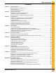
Table of Contents Contents Chapter 1 Safety Precautions ....................................................................................................................5 Safety Guidelines for Portable Dryers............................................................................................5 Cautionary Symbols ....................................................................................................................6 Safety Decals for Portable Dryers ..................................
Table of Contents Index .......................................................................................................................................65 GSI Group, LLC Limited Warranty............................................................................................
1 Safety Precautions Topics Covered in this Chapter ▪ Safety Guidelines for Portable Dryers ▪ Cautionary Symbols ▪ Safety Decals for Portable Dryers Safety Guidelines for Portable Dryers Safety guidelines are general-to-specific rules that promote safe practices in the grain drying environment and which must be respected at all times. Save these safety guidelines for future reference.
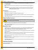
Chapter 1: Safety Precautions • To enable pre-season mode, click System→Control (Advanced)→Board Mode and then select Pre-season Mode. • Place the dryer in normal mode once inspections have been completed and you are ready to dry grain. IMPORTANT: If you power off the dryer while in pre-season mode, normal mode is automatically enabled the next time you power on the dryer. Make sure to reselect pre-season mode if further tests are required. Cleanliness • Keep the grain dryer clean at all times.
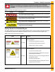
Chapter 1: Safety Precautions DANGER Make sure to familiarize yourself with the cautionary symbols prior to installing, operating, or servicing your equipment. Failure to do so might lead to serious injury or death. Table 1-1 Overview of the different cautionary symbols Symbol Description This symbol indicates an imminently hazardous situation which, if not avoided, will result in serious injury or death.
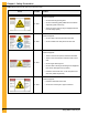
Chapter 1: Safety Precautions Table 1-2 Description of the grain dryer’s decals (cont'd.) Decal Decal No.
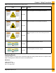
Chapter 1: Safety Precautions Table 1-2 Description of the grain dryer’s decals (cont'd.) Decal Decal No. Location This decal appears on the fan/heater access door DC-1949 This decal appears on the fan/heater access door DC-1959 This decal appears on each of the metering roll access doors DC-1950 This decal appears on the hitch tongue DC-1956 This decal appears on the hitch tongue DC-1954 Replacing Decals All decals located on your grain dryer must remain legible and clearly visible at all times.
NOTES 10 Pneg-1891 Portable Dryers
2 Installation Guidelines Topics Covered in this Chapter ▪ Guidelines for Transporting a Portable Dryer ▪ Guidelines for Placing a Portable Dryer ▪ Recommendations for a Single-Module Dryer Foundation Guidelines for Transporting a Portable Dryer To transport the dryer safely, follow the recommended guidelines and adhere to all state or provincial towing regulations. • Refer to Appendix A for the dryer transportation dimensions. • Ensure that the hitch height is between 14 and 17 in. (35.6 and 43.
Chapter 2: Installation Guidelines Figure 2-2 Hitch bolt with washer used for spacing A Washers B Locking nut C 0.75 in. (1.9 cm) Guidelines for Placing a Portable Dryer The location of existing equipment and local code requirements must be evaluated before installing the dryer. Things to consider when choosing a location: • Refer to Appendix A for dryer installation dimensions. • Consult all national and local electrical and gas codes to ensure dryer is located correctly.
Chapter 2: Installation Guidelines To prevent the dryer from overturning or moving laterally, the dryer must be secured to the foundation using anchor bolts or cables. Anchor bolts can be cast into the concrete slab and secured to the dryer legs. The dryer can also be secured using cables and turnbuckles that are fastened to the anchors that are installed at the edge of the concrete slab. Table 2-1 General reference for concrete materials needed for each size dryer foundation.
Chapter 2: Installation Guidelines Figure 2-4 Cross-section of the concrete for single-module dryers A 6 in. x 6 in. (15.2 cm x 15.2 cm) reinforcing mesh wire B Grade level C 0.5 in. (1.3 cm) number 4 reinforcing bar Figure 2-5 Side and rear view of the portable dryer 14 A Turnbuckle B Front fill option D 2 in. x 6 in. (5.8 cm x 15.2 cm) board E 8 in. X 8 in. X 16 in. (20.3 cm x 20.3 cm x 40.
3 Dryer Supports Topics Covered in this Chapter ▪ ▪ ▪ ▪ ▪ ▪ ▪ Guidelines for Supporting the Dryer with Concrete Blocks Guidelines for Supporting the Dryer with Leg Stands Leg Stand Spacing Installing Front and Rear Anchor Plates Installing a Leg Stand to the Dryer Basket Corner Installing a Leg Stand Along the Dryer’s Frame Installing the Leg Stands Behind the Hitch Frame Guidelines for Supporting the Dryer with Concrete Blocks Before filling the dryer with grain, the dryer frame must be supported with
Chapter 3: Dryer Supports Guidelines for Supporting the Dryer with Leg Stands Before filling the dryer with grain, the dryer frame must be supported with either concrete blocks or leg stands. Leg stands are optional and available in seven different sizes to accommodate various dryer heights. Leg Stand Height Options Leg stands are optional and must be ordered separately from your dryer. If you do not have leg stands, you must support the dryer with concrete blocks.
Chapter 3: Dryer Supports Leg Spacing for X-Stream Dryers Starting at both the front and back ends of the dryer (A and B), space legs 4 ft (1.22 m) apart working towards the center of the dryer. Spacing between center legs (C) can be 2 ft (0.61 m) or 4 ft (1.22 m), depending on the length of the dryer. Figure 3-3 Leg spacing on an X-Stream dryer NOTE: The number of dryer legs varies depending on the length of the dryer.
Chapter 3: Dryer Supports Installing a Leg Stand to the Dryer Basket Corner If not using concrete blocks, you must install leg stands to the dryer frame at the dryer basket corners to support the dryer. What You Should Know The additional width of the hitch bracket requires the use of an extra shim to install the legs located at the dryer frame corners. To install a leg stand to the dryer basket corner: 1. Remove the two existing bolts and nuts from the dryer frame corner (E and F). 2.
Chapter 3: Dryer Supports E S-3883 Original bolts installed on dryer (1/2 in. - 13 X 1 3/4 in. zinc grade 8 HHCS bolt) F S-6493 Original nuts installed on dryer (1/2 in. - 13 zinc grade 2 deformed lock nut) G D01–0007 Basket corner leg H D01–xxxx For leg stand, refer to Guidelines for Supporting the Dryer with Leg Stands, page 16 Installing a Leg Stand Along the Dryer’s Frame If not using concrete blocks, you must install leg stands to the dryer frame to support the dryer. 1.
Chapter 3: Dryer Supports Figure 3-6 Installing leg stands along dryer frame Callout Part number Description A S-3883 Original bolts installed on dryer (1/2 in. - 13 X 1 3/4 in. zinc grade 8 HHCS bolt) B S-6493 Original nuts installed on dryer (1/2 in. - 13 zinc grade 2 deformed lock nut) C D01–1221 Shim dryer stand to dryer NS S-2121 1/2 in. X 1 3/8 in. flat washer D S-8506 1/2 in. -13 zinc flange nut E S-8856 1/2 in. - 13 X 1 3/4 in.
Chapter 3: Dryer Supports 1. Position the leg stands (E) behind the hitch frame, and align them with the holes in the rear hitch cross channel (D). 2. Fasten the legs to the channel using two bolts (B), four washers (C), and two nuts (A) per each leg. Figure 3-7 Installing leg stands to the hitch assembly Part number Description A S-8506 1/2 in. - 13 zinc flange nut B S-8856 1/2 in. - 13 X 1 3/4 in. zinc grade 5 flange bolt C S-2121 1/2 in. X 1 3/8 in.
NOTES 22 Pneg-1891 Portable Dryers
4 Hitch Ladder Topics Covered in this Chapter ▪ ▪ ▪ ▪ ▪ Hitch Ladder Packages Installing the Hitch Ladder Support Bracket to the Hitch Channel Installing the Ladder Standoff Bracket to the Hitch Ladder Support Bracket Installing the Ladder to the Ladder Standoff Brackets Installing the End Cap to the Ladder Hitch Ladder Packages Hitch ladders are available in three different sizes. You must use the ladder package that is specific to your dryer size.
Chapter 4: Hitch Ladder Installing the Hitch Ladder Support Bracket to the Hitch Channel The hitch ladder is used to access the front of the dryer opposite of the control box side of the dryer. 1. Install the hitch ladder support bracket (A) to the center hole pattern on the hitch channel. 2. Fasten bracket (A) to the hitch channel, using flange bolts (B) and flange nuts (C).
Chapter 4: Hitch Ladder Installing the Ladder Standoff Bracket to the Hitch Ladder Support Bracket The ladder standoff brackets secures the ladder to the ladder support bracket, thus ensuring safe access to the front of the dryer. 1. Align the holes in the ladder standoff brackets (B) with the holes on the side of the hitch ladder support bracket (A). 2. Fasten the four standoff brackets (B) to the hitch ladder support bracket (A) using flange bolts (C) and flange nuts (D.
Chapter 4: Hitch Ladder Installing the Ladder to the Ladder Standoff Brackets Standoff brackets are used to support the ladder along it’s vertical length and secure the ladder to the equipment. 1. Install the carriage bolt (C) through the standoff wedge (B). 2. Hook the standoff wedge assembly (B) under the ladder edge (E). 3. Place the standoff bracket (A) onto the carriage bolt (C) and fasten in place with flange nut (D).
Chapter 4: Hitch Ladder Figure 4-4 End cap assembly Callout Part number Description A LDR-5011 Ladder end cap B S-7470 5/16 in. - 18 X 1 in. zinc grade 5 flange bolt C S-3611 5/16 in.
NOTES 28 Pneg-1891 Portable Dryers
5 Rear Access Ladder Topics Covered in this Chapter ▪ Installing the Rear Ladder Support Brackets ▪ Installing the Ladder Standoff Brackets to the Rear Ladder Support Brackets Installing the Rear Ladder Support Brackets The rear ladder support brackets attach directly to the dryer and support the ladder standoff brackets. 1. Locate the two upper rear ladder bracket installation locations (A) and remove the existing hardware (B and C). 2.
Chapter 5: Rear Access Ladder Figure 5-1 Installing the rear ladder support brackets Callout 30 Part number Description A D01–2691 Upper rear ladder bracket B NA Existing hardware — bottom bolt in door frame C NA Existing hardware — lower rear bracket D D01–2692 Lower rear bracket E S-9067 3/8 in. - 16 X 3/4 in. zinc grade 5 flange bolt F S-968 3/8 in.
Chapter 5: Rear Access Ladder Installing the Ladder Standoff Brackets to the Rear Ladder Support Brackets The ladder standoff brackets allow the ladder to be easily adjusted and secured to the dryer. 1. Install the ladder standoff brackets (A) to the lower rear ladder support bracket (D), using carriage bolts (B) and flange nuts (C). 2. Install the ladder standoff brackets (A) to the upper rear ladder support brackets (E), using carriage bolts (B) and flange nuts (C). 3.
NOTES 32 Pneg-1891 Portable Dryers
6 Installing the Wet Bin Topics Covered in this Chapter ▪ ▪ ▪ ▪ ▪ ▪ ▪ Raising the Load Auger Securing the Dryer Wet Bin Sides Installing the Belt Guard and Load Motor Installing the Drive Sheaves and Belts Installing the Belt Guard Cover Installing the Grain Intake Hopper The Parts of the Dryer Wet Bin Raising the Load Auger You must raise the load auger before you can install the dryer wet bin. 1. To raise the load auger: • For dryers eight ft (2.
Chapter 6: Installing the Wet Bin Figure 6-2 Turnbuckle location for dryers twelve ft (2.66 m) and longer B Lift kit turnbuckles for twelve ft (2.66 m) and longer dryers 2. Bolt the top angle brackets (D) to the angle brackets already installed, positioning the brackets backto-back. Brackets are located on the front and rear of the dryer, (see Figure 6-3, page 34). 3. Bolt the load auger housing channel (C) to the front and rear of the ends of the dryer wet bin.
Chapter 6: Installing the Wet Bin 1. At each end of the dryer, attach the end plate connectors to the corners of the dryer wet bin, (see Figure 6-4, page 35). 2. Raise the dryer wet grain bin sides (B) and secure them to the end plate connectors (A), (see Figure 6-5, page 36). NOTE: Do not connect the side of the dryer wet bin that is adjacent to the load auger motor. Leave this side open to allow for easy access when attaching the belt guard body.
Chapter 6: Installing the Wet Bin Figure 6-5 Connections for the dryer wet bin sides B Dryer wet bin side Installing the Belt Guard and Load Motor To protect you from the load motor belt, you must install the belt guard after installing the load motor. 1. Install the belt guard mounting bracket to the top of the dryer wet bin. 2. Lift the load motor and install 0.50 in. x 6 in.
Chapter 6: Installing the Wet Bin Figure 6-6 Bolt locations for Belt Guard Body Installing the Drive Sheaves and Belts To ensure that the load auger rotates, you must install the drive sheaves and belts. The motor turns the drive sheaves and belts, and the drive sheaves and belts turn the load auger. 1. Insert the key into the keyway on the auger drive shaft. 2. Place 16 inch sheave (D52–0001) on the auger drive shaft.
Chapter 6: Installing the Wet Bin 3. Insert the 1–1/2 inch split tapered Q1 bushing on the auger drive shaft and infix the bushing with a wooden or non-metal mallet. 4. Install three bolts into the bushing. If necessary, smooth the load auger drive shaft with hardware cloth. 5. Insert the key into keyway and slide the motor drive sheave onto the drive shaft of the load motor. 6. Secure the drive sheave with the setscrew. 7. Thread the two BX97 belts from the motor drive pulley to the 16 inch sheave. 8.
Chapter 6: Installing the Wet Bin Figure 6-8 Latches for the belt guard cover Installing the Grain Intake Hopper To ensure that the dryer receives the incoming wet grain, you must connect the grain intake hopper between the dryer wet bin and the equipment that supplies the wet grain. 1. Locate the hopper assembly (D01–0193) over the grain intake opening at the top rear of the dryer. 2. Connect the hopper assembly to the dryer wet grain bin by using six 1/4 in. x 3/4 in.
Chapter 6: Installing the Wet Bin Figure 6-10 The parts that make up the dryer wet bin 40 Pneg-1891 Portable Dryers
Chapter 6: Installing the Wet Bin Table 6-1 Part descriptions of the dryer wet bin Callout Part Number Quantity Description Dryer wet bin hardware package 1 D01-0465 Turnbuckle, 0.50 in. X 6 in.
NOTES 42 Pneg-1891 Portable Dryers
7 Power Supply Topics Covered in this Chapter ▪ ▪ ▪ ▪ Guidelines for Supplying Adequate Power Installing the Machine-to-Earth Grounding Rod Guidelines for Powering Auxiliary Conveyors Specifications for the Electrical Load on a Portable Dryer Guidelines for Supplying Adequate Power An adequate power supply and proper wiring are important factors for ensuring maximum performance and long life of the dryer.
Chapter 7: Power Supply CAUTION Do not install the machine-to-earth grounding rod into dry soil. The soil must be wet to ensure good contact with the surrounding soil, thereby making an appropriate ground. 1. Place the machine-to-earth grounding rod within 8 feet (2.4 meters) of the dryer. 2. Dig a hole large enough to hold 2 gallons (7.6 liters) of water. 3. Fill the hole with water and insert the rod through the water and into the ground. 4. Move the rod up and down, working the water into the ground.
Chapter 7: Power Supply Guidelines for Powering Auxiliary Conveyors Before you can operate the auxiliary conveyors, you must ensure that adequate power is available. • The auxiliary load and auxiliary unload augers or conveyors can be wired directly to the dryer. • If an auxiliary motor is larger than recommended, it must be powered from a source outside the dryer and must use a separate contactor and overload protection device for each motor.
Chapter 7: Power Supply Table 7-1 Specifications for the electrical load on a portable dryer (cont'd.) Dryer model Voltage Motor Load auger Unload auger 1 PH 230V 1114 D320 3 PH 220V 3 PH 440V Fan 1116 D370 3 PH 220V 3 PH 440V 3 PH 220V 1118 D400 3 PH 440V 3 PH 220V 1120 D460 3 PH 440V 5 26 5 26 10 to 17 78 Maximum amps with auxiliaries Minimum amps Recommended service in amps Branch breaker in amps 100 231 130 350 100 100 (2) 7.5 62 * Load auger 5 13.
Chapter 7: Power Supply Table 7-1 Specifications for the electrical load on a portable dryer (cont'd.) Dryer model HP Fuel Load Amps Load auger 7.5 20 Unload auger 7.5 20 Fan 30 74 (2) Auxiliary (2) 15 78 * Load auger 7.5 10 60 Unload auger 7.
Chapter 7: Power Supply Table 7-1 Specifications for the electrical load on a portable dryer (cont'd.) Dryer model Voltage Motor Load auger Unload auger Recommended service in amps Branch breaker in amps 100 26 Bottom Fan 10 to 12 48 100 (2) Auxiliary (2) 7.5 62 * Load auger 5 13.2 60 Unload auger 5 13.2 60 3 PH 220V Top Fan 100 286 178 400 100 15 39 Bottom Fan 10 to 12 33 (2) Auxiliary (2) 10 52 * Load auger 5 6.6 60 183 98.4 225 60 60 5 6.6 15 19.
Chapter 7: Power Supply Table 7-1 Specifications for the electrical load on a portable dryer (cont'd.) Dryer model Voltage HP Fuel Load Amps Load auger 10 26 Unload auger 10 26 25 64 Bottom Fan 10 to 12 33 60 (2) Auxiliary (2) 15 78 * Motor 3 PH 220V Top Fan 1226 2140 1218S 2181 350 90 60 60 25 32 Bottom Fan 10 to 12 16.5 (2) Auxiliary (2) 15 39 * Load auger 5 26 100 96 (2) Auxiliary 5 (2) 10 to 12 (2) 7.5 62 * Load auger 5 13.2 60 13.
Chapter 7: Power Supply Table 7-1 Specifications for the electrical load on a portable dryer (cont'd.) Dryer model Voltage HP Fuel Load Amps 7.5 31 31 156 (2) Auxiliary 7.5 (2) 10 to 17 (2) 7.5 62 * Load auger 7.5 20 90 Unload auger 7.5 20 (2) Fans (2) 15 78 (2) Auxiliary (2) 15 78 * Load auger 7.5 10 60 Unload auger 7.
8 Fuel Supply Topics Covered in this Chapter ▪ ▪ ▪ ▪ Guidelines for Connecting a Liquid Propane Supply Tank to a Dryer Specifications and Recommendations for Liquid Propane Guidelines for Connecting Natural Gas to a Dryer Specifications and Recommendations for Natural Gas Guidelines for Connecting a Liquid Propane Supply Tank to a Dryer When initially installing the dryer, you must connect a fuel source before you can operate the dryer.
Chapter 8: Fuel Supply Figure 8-1 Grain dryer connected to a liquid propane tank A Liquid propane gas supply tank B Liquid manifold connection C Liquid propane gas fuel line Specifications and Recommendations for Liquid Propane The liquid propane (LP) fuel line size and heater orifice size are determined by the dryer model heat capacity and fuel flow rate. Use the specifications chart that follows to select the appropriate equipment for your dryer.
Chapter 8: Fuel Supply Guidelines for Connecting Natural Gas to a Dryer When initially installing the dryer, you must connect a fuel source before you can operate the dryer. Natural gas (NG) is one possible fuel choice. • Operate the dryer on natural gas with a heat value of approximately 1000 BTU (880 kWper cubic foot). NOTE: The dryer is equipped with a natural gas supply pipe system connected to the heater solenoid valves.
Chapter 8: Fuel Supply Table 8-2 Specifications for natural gas (NG) (cont'd.) Dryer Model # Maximum Heat Capacity Fuel Line Size* Kilowatt Hours 2132 BTU Per Hour 9,750,000 2857 107 405 0.75 76.2 2140 10,500,000 6,000,000 115 66 435.3 250 0.75 0.75 76.2 76.2 1218S 2141 2181 3077 1759 7,000,000 2052 77 291 0.75 76.2 1220HX 490 2491 93 352 0.75 76.2 1220SX 500HX 510 8,500,000 8,500,000 9,750,000 2491 2857 93 107 352 405 0.75 0.75 76.2 76.
A Dryer Specifications Topics Covered in this Appendix ▪ ▪ ▪ ▪ ▪ ▪ Specifications for GSI Dryers Transport and Installation Dimensions for Single-Module GSI Dryers Specifications for FFI Dryers Transport and Installation Dimensions for Single-Module FFI Dryers Specifications for X-Stream Dryers Transport and Installation Dimensions for Single-Module X-Stream Dryers Specifications for GSI Dryers The specifications that follow list the detail information for each dryer model.
Appendix A: Dryer Specifications Table A-1 Specifications for the 1100 series portable dryers (cont'd.) Model # 1108 1112 1114 1116 1118 1120 1122 1126 Top Auger 8 in. 2 HP 2 HP 3 HP 5 HP 5 HP 7.5 HP 7.5 HP 10 HP (20 cm) diameter Capacity 2900 2900 3800 3800 3800 3800 3800 3800 (BPH) Bottom Auger 8 in. 1.5 HP 1.5 HP 3 HP 5 HP 5 HP 7.5 HP 7.
Appendix A: Dryer Specifications Table A-3 1Specifications for the 1200S series portable dryers (cont'd.) 1214(S or H) 1218(S or H) 1220(S or H) 1222(S or H) 1226(S or H) Model # Top Auger 8 in. (20 cm) 5 HP 5 HP 7.5 HP 7.5 HP 10 HP diameter Capacity (BPH) 3800 3800 3800 3800 3800 Bottom Auger 8 in. (20 cm) 5 HP 5 HP 7.5 HP 7.
Appendix A: Dryer Specifications Table A-4 GSI portable dryer transport and installation dimensions (cont'd.) Dryer Basket 1116 1118 1120 1122 1126 1214 1216 1218 1220 1222 1226 1214S 1218S 1220SH 1222SH 1226SH 58 A B Transport Height Installed Width 13 ft 5 in. (409 cm) 13 ft 5 in. (409 cm) 13 ft 5 in. (409 cm) 13 ft 5 in. (409 cm) 13 ft 5 in. (409 cm) 13 ft 5 in. (409 cm) 13 ft 5 in. (409 cm) 13 ft 5 in. (409 cm) 13 ft 5 in. (409 cm) 13 ft 5 in. (409 cm) 13 ft 5 in. (409 cm) 13 ft 5 in.
Appendix A: Dryer Specifications Specifications for FFI Dryers The specifications that follow list the detail information for each dryer model. You can reference these charts for items such as capacities, electrical loads, fan sizes, and auger dimensions.
Appendix A: Dryer Specifications Table A-6 Specifications for two Fan CFAB, H, and M portable dryer models Model # Total holding capacity (bushels) Grain column holding capacity (bushels) Fans 2141 14 ft (4.28 m) 2181 18 ft (5.49 m) 490 20 ft (6.10 m) 510 22 ft (6.71 m) 600 26 ft (7.92 m) 500 20 ft (6.10 m) 2221 22 ft (6.71 m) 650 26 ft (7.92 m) 381 490 528 582 688 528 582 688 329 423 454 500 591 454 500 591 (2) 36 in. (91 cm) 15 HP (2) 40 in. (102 cm) 25 HP (2) 36 in.
Appendix A: Dryer Specifications Figure A-4 Diagram of Dryer Dimensions Table A-8 FFI Transport and Installation Dimensions Dryer Basket 1 Fan CFAB Series Dryers 2 Fan CFAB Series Dryers 190 (8 ft) (2.44 m) 270 (12 ft) (3.66 m) 320 (14 ft) (4.28 m) 370 (16 ft) (4.88 m) 400 (18 ft) (5.49 m) 460 (20 ft) (6.10 m) 511 (22 ft) (6.71 m) 601 (26 ft) (7.92 m) 490 (20 ft) (6.10 m) 500H (20 ft) (6.10 m) 510 (22 ft) (6.71 m) 600 (26 ft) (7.92 m) 650 (26 ft) (7.
Appendix A: Dryer Specifications Table A-8 FFI Transport and Installation Dimensions (cont'd.) Dryer Basket 2120 (14 ft) (4.28 m) 2122 (16 ft) (4.88 m) 2125 (18 ft) C2100A (5.49 m) Series Dryers 2130 (20 ft) (6.10 m) 2132 (22 ft) (6.71 m) 2140 (26 ft) (7.92 m) A B Transport Height Installed Width 13 ft 5 in. (409 cm) 13 ft 5 in. (409 cm) 13 ft 5 in. (409 cm) 13 ft 5 in. (409 cm) 13 ft 5 in. (409 cm) 13 ft 5 in.
Appendix A: Dryer Specifications Table A-10 Specifications for the 1200S Series X-Stream Dryers (cont'd.) Model # 1220SX 1222SX 1226SX Bottom Auger 7.5 Hp 7.5 Hp 10 Hp 8 in. (20 cm) diameter VHD, 1 Hp VHD, 1 Hp VHD, 1 Hp Meter Roll Drive Capacity- MAX. Rate1 2800 3080 3640 (BPH) 1 Actual discharge rate is controlled by meter roll speed adjustment, at 5% to 100% of maximum rate. 2 Excludes auxiliary load and unload conveyor equipment.
Appendix A: Dryer Specifications Transport and Installation Dimensions for Single-Module X-Stream Dryers The dryer dimensions that follow help you determine the area that is needed for transporting and installing the dryer. Figure A-5 X-Stream dryer dimensions Table A-11 X-Stream dryer transport and installation dimensions Dryer basket 1220HX 1222HX 1226HX 1220SX 1222SX 1226SX 64 A B Transport height Installed width 13 ft 5 in. (409 cm) 13 ft 5 in. (409 cm) 13 ft 5 in. (409 cm) 13 ft 5 in.
Index Index D dryer placing ............................................................. 12 transporting.......................................................11 hitch frame....................................................... 20 spacing ............................................................ 16 liquid propane...................................................... 51 N F natural gas .......................................................... 53 foundation concrete.................................
NOTES 66 Pneg-1891 Portable Dryers
GSI Group, LLC Limited Warranty GSI Group, LLC Limited Warranty The GSI Group, LLC (“GSI”) warrants products which it manufactures to be free of defects in materials and workmanship under normal usage and conditions for a period of 12 months after sale to the original end-user or if a foreign sale, 14 months from arrival at port of discharge, whichever is earlier.
This equipment shall be installed in accordance with the current installation codes and applicable regulations which should be carefully followed in all cases. Authorities having jurisdiction should be consulted before installations are made. GSI Group 1004 E. Illinois St. Assumption, IL 62510-0020 Phone: 1-217-226-4421 Fax: 1-217-226-4420 www.gsiag.