Single Module Portable Dryer Parts Manual PNEG-1914 Date: 04-01-13 PNEG-1914
PNEG-1914 Single Module Portable Dryer
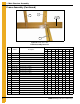
Table of Contents Contents Chapter 1 Main Structure Assembly ....................................................................................................................4 Frame Assembly ................................................................................................................................... 4 Frame, Auger Trough, Hopper Bulkheads - 4" Metering Roll ................................................................ 7 Bottom Auger - 4" Metering Rolls ..........................
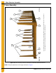
1. Main Structure Assembly The fan/heater end of the dryer is considered by GSI as the front end of the dryer. (The foreground of this photograph is the front end. Right and left sides are labeled above.) Right side 1 2 4 5 3 5 3 1a 5 3 4a 5 3 Left side Frame Assembly Figure 1A Frame Assembly (View from fan/heater end with hitch weldment removed.) NOTE: The parts pointed out on this page are listed on Page 6.
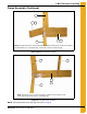
1. Main Structure Assembly Frame Assembly (Continued) 3 1 1a 4 2 4a NOTE: The right front corner is shown in the photo. For left front corner all parts are the same except for the hitch bracket (use 1a for the left side), and the frame rail (use 4a for the left side). Figure 1B Right Front Corner of Frame 3 5 4a 4 2 NOTE: The left rear corner is shown in the photo. For right rear corner all parts are the same except for the frame rail (use 4 for the right side).
1. Main Structure Assembly Frame Assembly (Continued) 3 5 4a 4 2 Figure 1D Center Cross Ties Frame Assembly Parts List Qty Ref # 6 Part # Description 1108 1112 1114 1116 1118 1120 1122 1126 D190 D270 D320 D370 D400 D460 D511 D601 1 D01-0012-BK Hitch Bracket - R.H. Black 1 1 1 1 1 1 1 1 1a D01-0011-BK Hitch Bracket - L.H.
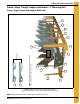
1. Main Structure Assembly Frame, Auger Trough, Hopper Bulkheads - 4" Metering Roll 10 7 6 9 5 4 NOTE: The hole pattern of the plenum closure door angles. This will distinguish between L.H. and R.H. 2 1 6 3 8 11 5 9 4 6 Frame, Auger Trough and Hopper Bulkheads Figure 1E Dryer Frame and Lower Basket Assembly (View from the front end of the dryer looking down the left side.) NOTE: The parts pointed out on this page are listed on Page 10.
1. Main Structure Assembly 12 6 9 3 3 4 6 12 13 12 14 15 Center hanger bearing support and cross channel seal plate. 11a 5 12 3 9 6 4 20 19 6 Wooden metering roll support bearing. The metering roll sections are spliced together with a metering roll splice shaft (part #D31-0046) that passes through the support bearing assembly.
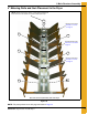
1. Main Structure Assembly 4" Metering Rolls and their Placement in the Dryer NOTE: Ref #22 at the rear of dryer is a front section metering roll that is used as a rear section on 16 and 20 feet dryers only. 22 24 Metering roll bearing Ref #16, 17 and 18 on Page 10. 23 23 Metering Roll bearing Ref #16, 17 and 18 on Page 10. 23 23 Metering roll bearing Ref #16, 17 and 18 on Page 10. 22 22 This end is the front (fan/heater) end of the dryer.
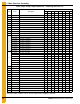
1. Main Structure Assembly Frame, Auger Trough, Hopper Bulkheads - 4" Metering Roll Parts List Qty Ref # Part # Description 1108 1112 1114 1116 1118 1120 1122 1126 D190 D270 D320 D370 D400 D460 D511 D601 1 D01-1136Y Plenum Closure Door Angle, R.H. 3 5 6 7 8 9 10 12 2 D01-1136X Plenum Closure Door Angle, L.H.
1. Main Structure Assembly Bottom Auger - 4" Metering Rolls 1 2 2 3 2 4" Metering roll bottom auger (View from center of dryer to the forward end.) 4 4" Metering roll bottom auger (View from center of dryer to the rear end.) 7 8 5 7 6 4" and 7" Metering roll Bottom auger rear bearing 4" Metering roll bottom auger Center bearing and support Figure 1H NOTE: The parts pointed out on this page are listed on Page 12.
1.
1. Main Structure Assembly Inside (Plenum) Screens, Plenum Closure Doors - 4" Metering Roll Plenum Screens and Bulkheads (View from Front End) 2 3b 4 3a 5 1 5 6 16 7 10 8 7 11 13 20 14 18 9 19 12 15 10 20a 21 22 This photograph was taken before the front plenum end panel and outer screens were installed in order to get a good view of the inside screens and bulkheads. Plenum closure door. There are two (2) different plenum closure doors.
1.
1. Main Structure Assembly Outer Screens - 4" Metering Roll Access Doors 3 3a * * 2 4 3 * 2 4 3 1b 3a 5 1a 9 10 6 14 12 7 13 8 9 10 11 See Figure 1L on Page 14 *NOTE: Ref #3 is pointing to the top edge angle gusset. There are two (2) types of gusset on the dryer. The photo on top right will help distinguish the difference between the two. The arrows are pointing to a tab on the gusset that makes them different (tabs are “bent” up in photo).
1. Main Structure Assembly Outer Screens - 4" Metering Roll Access Doors (Continued) 19 15 16 18 17 20 Figure 1L Metering Roll Access Door Outer Screens - 4" Metering Roll Access Doors Parts List Qty Ref # Description 1108 1112 1114 1116 1118 1120 1122 1126 D190 D270 D320 D370 D400 D460 D511 D601 1a D01-2466 Column End Panel - R.H. Front 1 1 1 1 1 1 1 1 1b D01-2467 Column End Panel - L.H.
1. Main Structure Assembly Clean Out Doors - 4" Metering Roll 11 1 9 13 3 2 4 5 Front and rear handle mechanisms (rear shown in photo) 3 11 3a 5 4 10 2 6 7 Clean out door handle mechanism 11 NOTE: Ref #9, 10 and 11 together create the clean out door assembly. There are three (3) different clean out door assemblies that are used on GSI Network dryers: 1) 3 Column clean out door assembly (D51-0077). Ref #8a on the part # listing (Page 18). 2) 4 Column clean out door assembly (D11-0032).
1. Main Structure Assembly Clean Out Doors - 4" Metering Roll (Continued) 3a 14 1a 14 3a 11 4 5 2 14 Figure 1N Center Handle Mechanisms (This handle mechanism straddles the center cross channels.
1. Main Structure Assembly Frame and Lower Basket - 7" Metering Roll 1 1 2 3 3 4 9 3 7 5 9 9 7 8 1 4a 3 Metering roll access doors 6 1 Grain diverter and metering roll pan assemblies. This photo was taken before screens were installed looking down the inside of the grain column. 10 11 10 11 12 13 12 11 14 14a 10 Figure 1O NOTE: The parts pointed out on this page are listed on Page 23 and Page 24.
1. Main Structure Assembly Frame and Lower Basket - 7" Metering Roll (Continued) 10 15 Auger trough panels Grain flow regulators. This photo was taken with the metering roll access door (ref #13) removed and looking down at the unload auger. Clean out door assembly. (See Page 21.) 16 11 11 17 12 12 12 16 Figure 1P NOTE: The parts pointed out on this page are listed on Page 23 and Page 24.
1. Main Structure Assembly Clean Out Doors - 7" Metering Roll 18 28 30 20 19 21 22 Front and rear handle mechanisms (rear shown in photo) 26 21 22 20 20a 28 24 23 19 Clean out door handle mechanism 30 29 27 26 28 27 28 Clean out door hinge Figure 1Q NOTE: The parts pointed out on this page are listed on Page 23 and Page 24.
1. Main Structure Assembly Clean Out Doors - 7" Metering Roll (Continued) 31 18a 31 21 20a 19 22 28 31 Figure 1R Center Handle Mechanisms (This handle mechanism stradles the center cross channels.) NOTE: Ref # 26, 27 and 28 together create the clean out door assembly. There are three (3) different clean out door assemblies that are used on FFI Dri-Tek dryers. 1. 3 Column clean out door assembly (D51-0077). Ref # 25A on the part # listing on Page 24. 2. 4 Column clean out door assembly (D11-0032).
1. Main Structure Assembly Frame, Lower Basket and Clean Out Doors - 7" Metering Roll Parts List Ref # Part # 1108 1112 1114 1116 1118 1120 1122 1126 D190 D270 D320 D370 D400 D460 D511 D601 Description 1 401-5259-7 Hopper Bulkhead - 7" Metering Roll 6 10 12 14 16 18 20 24 2 D01-0004 Gusset Plate 10 4 6 8 20 22 24 28 3 D01-0007-BK Corner Leg Portable Dryer, Black 4 6 6 6 6 6 8 8 4 D11-0005-BK Frame Rail, 8' R.H.
1.
1. Main Structure Assembly 7" Metering Rolls 2 3 5 4 1 Phenolic bearings Metering roll layout 7 6 8 Metering roll splice shaft Figure 1S NOTE: The parts pointed out on this page are listed on Page 26.
1. Main Structure Assembly 7" Metering Rolls Parts List Ref # Front Metering Roll Middle Metering Roll Rear Metering Roll 26 Part # 1108 1112 1114 1116 1118 1120 1122 1126 D190 D270 D320 D370 D400 D460 D511 D601 2 2 Description 1 025-1217-6 Metering Roll Exterior 7' x 95.69" 1 025-1215-0 Metering Roll Exterior 7' x 71.313" 1 025-1216-8 Metering Roll Exterior 7' x 95.34" 1 025-1219-2 Metering Roll Exterior 7' x 119.
1. Main Structure Assembly Bottom Auger - 7" Metering Roll 3 2 5 4 11 1 Bottom auger center bearing 12 13 6 Bottom auger layout 7 8 14 11 9 12 13 10 Figure 1T NOTE: The parts pointed out on this page are listed on Page 28.
1.
1. Main Structure Assembly Bottom Auger - Rear Hanger Bearing Assembly Discharge bearing plate with discharge box removed. 2 1 3 Rear hanger bearing (See Page 27 for a parts breakdown.
1. Main Structure Assembly Plenum Screens - 7" Metering Roll 2 4 3a 1 5 6 3b Figure 1V Plenum Screens - 7" Metering Roll Parts List Ref # 30 Part # 1108 1112 1114 1116 1118 1120 1122 1126 D190 D270 D320 D370 D400 D460 D511 D601 Description 1 D31-0055 Column Bulk Head 6 10 12 14 16 18 20 24 2 D01-0101 Garner Bulkhead 6 10 12 14 16 18 20 24 3a D01-2466 Column End Panel - R.H. Front 1 1 1 1 1 1 1 1 3b D01-2467 Column End Panel - L.H.
1. Main Structure Assembly Outside Screens - 7" Metering Roll 1 1 2 3b 3a 5 6 4 7 8 7 8 Figure 1W NOTE: The parts pointed out on this page are listed on Page 32.
1. Main Structure Assembly Outside Screens - 7" Metering Roll Parts List Ref # 32 Part # 1108 1112 1114 1116 1118 1120 1122 1126 D190 D270 D320 D370 D400 D460 D511 D601 Description 1 D01-0127 Screen, Roof, GA, 094 8 12 14 16 18 20 22 26 2 D31-0013 Screen, Outside Wall Sheet 8 12 14 16 18 20 22 26 3a D01-2466 Column End Panel - R.H. Front 1 1 1 1 1 1 1 1 3b D01-2467 Column End Panel - L.H.
1. Main Structure Assembly Front and Rear Plenum End Panels 2 3 1d 1c 11 3 1b 3 4 1a Rear plenum end panels 10 5 6 9 6a Front end panels and support arms 7 8 Figure 1X NOTE: The parts pointed out on this page are listed on Page 34.
1. Main Structure Assembly Front and Rear Plenum End Panels Parts List 1108 Ref # Part # 1112 1114 1116 1118 1120 1122 1126 Description D190 D270 D320 D370 D400 D460 D511 D601 1a D01-2466 Column End Panel - R.H. Front 1 1 1 1 1 1 1 1 1b D01-2467 Column End Panel - L.H. Front 1 1 1 1 1 1 1 1 1c D01-2476 Column End Panel - R.H. Rear 1 1 1 1 1 1 1 1 1d D01-2477 Column End Panel - L.H.
1. Main Structure Assembly Plenum Access Door - GSI (D04-0940-Y) Figure 1Y NOTE: The parts pointed out on this page are listed on Page 36.
1.
1. Main Structure Assembly Plenum Access Door - GSI (D04-0940-F) Figure 1Z NOTE: The parts pointed out on this page are listed on Page 38.
1.
1. Main Structure Assembly Fan Access Step 5 6 7 8 2 1 3 4 Figure 1AA Fan Access Step Parts List Qty Ref # Part # Description Fan Access Step Kit 1108 1112 1114 1116 1118 1122 1126 D190 D270 D320 D370 D400 D460 D511 D601 1 1 1 1-4 D01-1198 1 D01-1168 Fan Access Step L.H. Mount 1/Kit 2 D01-1166 Fan Access Step 1/Kit 3 D51-0022 Support, Control Panel 1/Kit 4 D01-1167 Fan Access Step R.H.
1.
1.
1. Main Structure Assembly Top Auger with Wet Bin Assembly 2 1 1 3a 4 6 7 5 8 1 3 10 11 9 12 Top auger with wet bin (switch paddle end) 26 9 14 13 Top auger (fill end) 14a Figure 1AD NOTE: The parts pointed out on this page are listed on Page 44.
1. Main Structure Assembly Top Auger with Wet Bin Assembly (Continued) 17 16 15 21 22 20 19 10 21 18 22 Top auger bearing support 16 7 23 25 24 7 Top auger bearing support (inside view) Figure 1AE NOTE: The parts pointed out on this page are listed on Page 44.
1. Main Structure Assembly Top Auger with Wet Bin Assembly Parts List Qty Ref # Description 1 D01-1521 Wet Bin Side, 4' Side Galv. Perf. 1 D01-1522 Wet Bin Side, 6' Side Galv. Perf. 2 D01-0103 Tilt Switch Shaft D21-0003 Top Edge Angle 71-7/8" D31-0004 Top Edge Angle 95-7/8" D01-0168 Top Edge Angle 119-7/8" 3a D31-0003 Top Edge Angle Splice 4 325-1688-2 Top Angle Bracket Front and Rear 5 D01-0147 Top Auger Housing Hinge L.H.
2. Auger and Metering Roll Drive Trains 4" Bottom Auger Drive 9 1 10 2 8 3 7 4 6 5 11 11 Bottom auger drive components 12 5 13 13 14 Bottom auger motor and motor mount 16 15 4 13 18 16 6 Forward drive tension adjustment 17 Rear drive tension adjustment Figure 2A NOTE: The parts pointed out on this page are listed on Page 47.
2. Auger and Metering Roll Drive Trains 4" Bottom Auger Drive (Continued) 21 22 19 20 Figure 2B Bottom Auger and Metering Roll Drive Guard NOTE: The parts pointed out on this page are listed on Page 47.
2. Auger and Metering Roll Drive Trains 4" Bottom Auger Drive Parts List Qty Ref # Part # Description 1108 1112 1114 1116 1118 1120 1122 1126 D190 D270 D320 D370 D400 D460 D511 D601 1 D01-1376 Bottom Front Angle Bracket 1 1 1 1 1 1 1 1 2 D02-0067 V-Belt BX85 2 2 2 2 2 2 2 2 1 1 1 1 1 1 1 1 2 3 MHC00490 V-Belt BX82 D03-0174 Sheave 2.5D x 7/8" Bore 2818-2 Sheave 2 Grade 3.35D x 1-1/8" Bore D62-0003 Sheave 2 Grade 4.
2. Auger and Metering Roll Drive Trains Top Auger Drive 1 6 Belt guard upper mount 1 4 2 3 5 14 Top auger drive components 12 13 Top auger belt guard cover Figure 2C NOTE: The parts pointed out on this page are listed on Page 49.
2.
2. Auger and Metering Roll Drive Trains 4" Metering Roll Drive 8 7 1 2 4 5 3 6 7a SCR Motor/reduction drive and motor mount assembly 12 17 9 14 15 16 11 10 8 9 12 13 14 14 4" Metering roll drive train components Figure 2E NOTE: The parts pointed out on this page are listed on Page 51.
2. Auger and Metering Roll Drive Trains 4" Metering Roll Drive (Continued) 18 18 19 19 20 21 Rear metering roll bearing Front metering roll bearing Figure 2F 4" Metering Roll Drive Parts List Qty Ref # 1 Part # Description 1108 1112 1114 1116 1118 1120 1122 1126 D190 D270 D320 D370 D400 D460 D511 D601 6 6 6 6 6 8 8 D01-0007 Corner Leg Portable Dryer 4 D11-0004-BK Frame Rail, 8' L.H. Black 1 D51-0001-BK Frame Rail, 12' L.H. Black D21-0010-BK Frame Rail, 14' L.H.
2. Auger and Metering Roll Drive Trains 7" Bottom Auger Drive 1 2 3 6 4 5 8 7 9 8 Bottom auger drive components 10 11 7 10 12 8 9 Motor and mount Motor mount adjustment Figure 2G NOTE: The parts pointed out on this page are listed on Page 53.
2. Auger and Metering Roll Drive Trains 7" Bottom Auger Drive Parts List Qty Ref # Part # Description 1108 1112 1114 1116 1118 1120 1122 1126 D190 D270 D320 D370 D400 D460 D511 D601 1 D01-1949 Offset Plate Front Belt Guard 1 1 1 1 1 1 1 1 D02-0067 V-Belt BX85 2 2 MHC00490 V-Belt BX82 2 2 2 2 2 2 D03-0174 Sheave 2 Grade 3.35D x 1-1/8" Bore 2818-2 Sheave 2 Grade 3.35D x 1-1/8" Bore 1 1 1 D62-0003 Sheave 2 Grade 4.
2. Auger and Metering Roll Drive Trains 7" Metering Roll Drive 5 6 7 4 Metering roll drive component layout 9 8 1 2a 2 3 Metering roll bearing with drive shaft Figure 2H NOTE: The parts pointed out on this page are listed on Page 56.
2. Auger and Metering Roll Drive Trains 7" Metering Roll Drive (Continued) 21 20 Metering roll motor 10a 14 15 10b 11 12 16 19 17 13 18 Figure 2I NOTE: The parts pointed out on this page are listed on Page 56.
2.
3. Fan/Heaters Fan/Heater Housing Assembly Figure 3A Fan Housing Assembly 36"-15 HP, VN2 (FHA-3615-VN2) Figure 3B Fan Housing Assembly 36"-15 HP, VN2 (FHA-3615-VN2) NOTE: The parts pointed out on this page are listed on Page 59.
3. Fan/Heaters Fan/Heater Housing Assembly (Continued) Figure 3C Fan Housing Assembly 40"-15 HP, VN2 (FHA-4015-VN2) Figure 3D Fan Housing Assembly 40"-15 HP, VN2 (FHA-4015-VN2) NOTE: The parts pointed out on this page are listed on Page 59.
3.
3. Fan/Heaters Fan/Heater Housing Assembly (Continued) Figure 3E Burner Access Door Assembly Burner Access Door Assembly Parts List Ref # Part # Description Qty 1 401-5759-6-B Access Door - Galv. Fan Black 1 2 069-1303-2 Glass, Sight AH24/28 1 3 S-6673 Flat Washer 1/4" SS 4 4 S-4614 Bolt, HHCS 1/4"-20 x 1/2" SS 4 5 S-7307 Nylock Nut 1/4"-20 SS 4 6 S-6606 Flange Bolt 5/16"-18 x 3/4" ZN Grade 5 3 7 090-1709-6 Retainer Nut 5/16"-18 x 0.
3.
3. Fan/Heaters Air Mixer Assemblies 1 1a 2 Figure 3H Air Mixer Assemblies (36'' Air mixer shown in photo.
3. Fan/Heaters Flame Probe, Ignitor and Burner Assemblies Figure 3I Switch Kit, Air Velocity Sensor, VN2 (D04-0906) Switch Kit, Air Velocity Sensor, VN2 (D04-0906) Parts List Ref # Part # Description Qty 1 TD-101361 Housing Assembly, Air Switch, TD + PD 1 2 D03-0167 Air Pressure Switch 1 3 D03-0166 Switch, Pressure Nut BEC Style 1 4 D03-0649 Elbow, 1/4" Clamp x 1/8" NPT Brass 1 5 FH-1310 Connector, Cord 1 6 006-1236-6 Lock Nut 1/2" NPT Nylon 1 7 HF-7463 Tube, 1/4" O.D.
3.
3. Fan/Heaters Flame Probe, Ignitor and Burner Assemblies (Continued) Figure 3K Ignitor Assembly, Portable Dryer, 1/8" Gap (TF-1558) Ignitor Assembly, Portable Dryer, 1/8" Gap (TF-1558) Parts List Ref # Part # Description Qty 1 HF-7204 Dual Probe Ignitor Bracket 1 2 CD-0238 Igniter, Flame 2 3 HF-7201 Ignitor Half Clamp 2 4 S-2786 Screw, TCSF #8-32 x 3/8" PHP ZN 2 5 S-4614 Bolt, HHCS 1/4"-20 x 1/2" SS 2 6 S-4615 Hex Nut 1/4"-20 302 18.
3.
3. Fan/Heaters Flame Probe, Ignitor and Burner Assemblies (Continued) See Figure 3L on Page 66 for instructions on bending flame probe rod.
3. Fan/Heaters Flame Probe, Ignitor and Burner Assemblies (Continued) Figure 3N Burner Sub-Assembly, 36" PD Fan/Heater (D04-0806) Burner Sub-Assembly, 36" PD Fan/Heater (D04-0806) Parts List Ref # 68 Part # Description Qty 1 D04-0805 Burner Weldment, 36" PD Fan/Heater 1 2 D04-0899 Burner Cup Assembly, with Flame Tubes 36" 3-4.5MBTU 1 3 S-6673 Flat Washer 1/4" SS 3 4 S-4616 Bolt, HHCS 1/4"-20 x 1-1/4" 302 18.
3.
3. Fan/Heaters Flame Probe, Ignitor and Burner Assemblies (Continued) Figure 3P Burner Sub-Assembly, 40" PD Fan/Heater (D04-0897) Burner Sub-Assembly, 40" PD Fan/Heater (D04-0897) Parts List Ref # 70 Part # Description Qty 1 D04-0896 Burner Weldment, 40" PD Fan/Heater 1 2 D04-0803 Burner Cup Assembly, with Flame Tubes 42" 6-10MBTU 1 3 S-6673 Flat Washer 1/4" SS 3 4 S-4616 Bolt, HHCS 1/4"-20 x 1-1/4" 302 18.
3. Fan/Heaters Flame Probe, Ignitor and Burner Assemblies (Continued) Figure 3Q Burner Sub-Assembly, 42" PD Fan/Heater (D04-0802) Burner Sub-Assembly, 42" PD Fan/Heater (D04-0802) Parts List Ref # Part # Description Qty 1 D04-0801 Burner Weldment, 42" PD Fan/Heater 1 2 D04-0803 Burner Cup Assembly, with Flame Tubes 42" 6-10MBTU 1 3 S-6673 Flat Washer 1/4" SS 3 4 S-4616 Bolt, HHCS 1/4"-20 x 1-1/4" 302 18.
3.
3. Fan/Heaters Fan/Heater Assembly Figure 3S Fan/Heater 36" 12 HP 230V 1 PH LP, VN2, CSA (3616V-2L-U) NOTE: The parts pointed out on this page are listed on Page 80.
3. Fan/Heaters Fan/Heater Assembly (Continued) Figure 3T Fan/Heater 36" 12 HP 230V 1 PH LP, VN2, CSA (3616V-2L-U) NOTE: The parts pointed out on this page are listed on Page 80.
3. Fan/Heaters Fan/Heater Assembly (Continued) Figure 3U Fan/Heater 36" 12 HP 230V 1 PH LP, VN2, CSA (3616V-2L-U) NOTE: The parts pointed out on this page are listed on Page 80.
3. Fan/Heaters Fan/Heater Assembly (Continued) Figure 3V Fan/Heater 36" 12 HP 230V 1 PH LP, VN2, CSA (3616V-2L-U) NOTE: The parts pointed out on this page are listed on Page 80.
3. Fan/Heaters Fan/Heater Assembly (Continued) Figure 3W Fan/Heater 36" 12 HP 230V 1 PH LP, VN2, CSA (3616V-2L-U) NOTE: The parts pointed out on this page are listed on Page 80.
3. Fan/Heaters Fan/Heater Assembly (Continued) Figure 3X Fan/Heater 36" 12 HP 230V 1 PH LP, VN2, CSA (3616V-2L-U) NOTE: The parts pointed out on this page are listed on Page 80.
3. Fan/Heaters Fan/Heater Assembly (Continued) Figure 3Y Fan/Heater 36" 12 HP 230V 1 PH LP, VN2, CSA (3616V-2L-U) NOTE: The parts pointed out on this page are listed on Page 80.
3.
3. Fan/Heaters Fan/Heater Assembly (Continued) Figure 3Z Fan/Heater 40" 15 HP 230V 3 PH LP VN2 (4015V-2L-U) NOTE: The parts pointed out on this page are listed on Page 87.
3. Fan/Heaters Fan/Heater Assembly (Continued) Figure 3AA Fan/Heater 40" 15 HP 230V 3 PH LP VN2 (4015V-2L-U) NOTE: The parts pointed out on this page are listed on Page 87.
3. Fan/Heaters Fan/Heater Assembly (Continued) Figure 3AB Fan/Heater 40" 15 HP 230V 3 PH LP VN2 (4015V-2L-U) NOTE: The parts pointed out on this page are listed on Page 87.
3. Fan/Heaters Fan/Heater Assembly (Continued) Figure 3AC Fan/Heater 40" 15 HP 230V 3 PH LP VN2 (4015V-2L-U) NOTE: The parts pointed out on this page are listed on Page 87.
3. Fan/Heaters Fan/Heater Assembly (Continued) Figure 3AD Fan/Heater 40" 15 HP 230V 3 PH LP VN2 (4015V-2L-U) NOTE: The parts pointed out on this page are listed on Page 87.
3. Fan/Heaters Fan/Heater Assembly (Continued) Figure 3AE Fan/Heater 40" 15 HP 230V 3 PH LP VN2 (4015V-2L-U) Figure 3AF Fan/Heater 40" 15 HP 230V 3 PH LP VN2 (4015V-2L-U) NOTE: The parts pointed out on this page are listed on Page 87.
3.
3. Fan/Heaters Fan/Heater Assembly (Continued) Figure 3AG Fan/Heater 42" 20 HP 230V 3 PH LP, VN2 (4220V-2L-U) NOTE: The parts pointed out on this page are listed on Page 95.
3. Fan/Heaters Fan/Heater Assembly (Continued) Figure 3AH Fan/Heater 42" 20 HP 230V 3 PH LP, VN2 (4220V-2L-U) NOTE: The parts pointed out on this page are listed on Page 95.
3. Fan/Heaters Fan/Heater Assembly (Continued) Figure 3AI Fan/Heater 42" 20 HP 230V 3 PH LP, VN2 (4220V-2L-U) NOTE: The parts pointed out on this page are listed on Page 95.
3. Fan/Heaters Fan/Heater Assembly (Continued) Figure 3AJ Fan/Heater 42" 20 HP 230V 3 PH LP, VN2 (4220V-2L-U) NOTE: The parts pointed out on this page are listed on Page 95.
3. Fan/Heaters Fan/Heater Assembly (Continued) Figure 3AK Fan/Heater 42" 20 HP 230V 3 PH LP, VN2 (4220V-2L-U) NOTE: The parts pointed out on this page are listed on Page 95.
3. Fan/Heaters Fan/Heater Assembly (Continued) Figure 3AL Fan/Heater 42" 20 HP 230V 3 PH LP, VN2 (4220V-2L-U) NOTE: The parts pointed out on this page are listed on Page 95.
3. Fan/Heaters Fan/Heater Assembly (Continued) Figure 3AM Fan/Heater 42" 20 HP 230V 3 PH LP, VN2 (4220V-2L-U) NOTE: The parts pointed out on this page are listed on Page 95.
3.
3.
3.
3.
3.
3.
3.
3.
3.
3.
3.
3.
3.
3.
4. Dryer Electrical Conduits Upper Junction Box, Top Auger Motor Conduit and Operator Light 1 11 4 3 5 6 Top auger motor conduit 2 7 9 9 1 12 10 2 10 1 15 2 Upper junction box 11 8 Fill switch assembly (installed) Operator light 13 14 9 Ref #9-15 are components of the mercury switch box assembly (fill switch assembly) part #D01-0192.
4. Dryer Electrical Conduits Air Switch Assembly 3 7 9 4 8 2 5 6 Air switch assembly (internal parts) 1 Air switch assembly (D01-0672) 10 11 12 1-9 10 Air switch assembly (installed) Figure 4B Air Switch Assembly Parts List Ref # 110 Part # Description Qty 1-9 D01-0672 Air Switch Assembly 1/Dryer 1 D01-0671 Air Switch Box Conduit Half 2/Assembly 2 D01-0670 Air Switch Box Face Plate 1/Assembly 3 DC-1103 Decal, Air Pressure Adjustment 1/Assembly 4 D03-0177 Grommet, 11/16" I.
4. Dryer Electrical Conduits Right and Left Grain and Plenum High-Limits Right grain high-limit Left grain high-limit 8 11 Plenum high-limit 7 10 Right grain and plenum high-limit thermostat enclosures 4 9 Left grain high-limit thermostat enclosure Grain temperature thermistor. There are two (2) thermistors in each (right and left) grain high-limit thermostat assemblies.
4.
4. Dryer Electrical Conduits Lower Junction Box, Metering Roll Motor Conduit and Rear Discharge Conduit 7 3 8 5 4 9 6 6 2 5 1 7 2 10 1 4 Conduit to metering roll motor. (See metering roll motor conduit connection below.) Lower junction box (right) 8 1 Lower junction box (left) Conduit to metering roll speed sensor and rear discharge switch. (See photos below and on Page 114.
4.
5. Control Boxes Fan/Heater Electrical Box Figure 5A Figure 5B NOTE: The parts pointed out on this page are listed on Page 117.
5. Control Boxes Fan/Heater Electrical Box (Continued) Figure 5C NOTE: The parts pointed out on this page are listed on Page 117.
5.
5. Control Boxes Control Box Control Panel Figure 5D Figure 5E NOTE: The parts pointed out on this page are listed on Page 120.
5. Control Boxes Control Box Control Panel (Continued) Figure 5F Figure 5G NOTE: The parts pointed out on this page are listed on Page 120.
5.
5.
5. Control Boxes Upper Control Box See Figure 5J on Page 123 See Figure 5L on Page 124 See Figure 5K on Page 124 See Figure 5J on Page 123 Figure 5I NOTE: The parts pointed out on this page are listed on Page 125.
5. Control Boxes Upper Control Box (Continued) Figure 5J NOTE: The parts pointed out on this page are listed on Page 125.
5. Control Boxes Upper Control Box (Continued) Figure 5K Figure 5L NOTE: The parts pointed out on this page are listed on Page 125.
5. Control Boxes Upper Control Box Component Parts List Ref # 1 Part # D01-2717 Description DCB Power Box Back Panel VN2 2 (See Chart on Pages 126-144.) 3 (See Chart on Pages 126-144.) 4 (See Chart on Pages 126-144.) 5 (See Chart on Pages 126-144.) 6 (See Chart on Pages 126-144.) 7 (See Chart on Pages 126-144.) 8 (See Chart on Pages 126-144.) 9 (See Chart on Pages 126-144.) 10 (See Chart on Pages 126-144.
5.
5.
5.
5.
5.
5.
5.
5.
5.
5.
5.
5.
5.
5.
5.
5.
5.
5.
5.
6. Warranty GSI Group, LLC Limited Warranty The GSI Group, LLC (“GSI”) warrants products which it manufactures to be free of defects in materials and workmanship under normal usage and conditions for a period of 12 months after sale to the original end-user or if a foreign sale, 14 months from arrival at port of discharge, whichever is earlier.
This equipment shall be installed in accordance with the current installation codes and applicable regulations, which should be carefully followed in all cases. Authorities having jurisdiction should be consulted before installations are made. GSI Group 1004 E. Illinois St. Assumption, IL 62510-0020 Phone: 1-217-226-4421 Fax: 1-217-226-4420 www.gsiag.