Roof Exhaust Fan Installation & Operation Owner’s Manual PNEG-524 Date: 04-11-07 PNEG-524
Check List 1. All wire connections 2. Tip clearance on blade 3. Fan blade torqued to torque specs 4. Grill guard in place and tight 5. Motor rotation correct 6. Running amperage 7. Vibration 8. All fasteners tight 9. Indicator light 10. All decals and serial number tag 11. Aesthetic appearance 12. Manual in control box 13.
Table of Contents Contents Chapter 1 Safety ................................................................................................................................. 4 Roof Damage Warning and Disclaimer ............................................................................... 4 Roof Exhauster Fan Operation ........................................................................................... 4 Safety Alert Symbol ...........................................................................
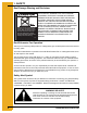
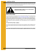
1. SAFETY Roof Damage Warning and Disclaimer CAUTION! CAUTION! Excessive vacuum (or pressure) may damage roof. Use positive aeration system. Make sure all roof vents are open and unobstructed. Start roof fans when supply fans are started. Do not operate when conditions exist that may cause roof vent icing. DC-969 GSI DOES NOT WARRANT ANY ROOF DAMAGE CAUSED BY EXCESSIVE VACUUM OR INTERNAL PRESSURE FROM FANS OR OTHER AIR MOVING SYSTEMS.
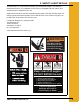
2. SAFETY ALERT DECALS The GSI Group, Inc. recommends contacting your local power company, and having a representative survey your installation so the wiring is compatible with their system, and adequate power is supplied to your unit. Safety decals should be read and understood by all people in the grain handling area. The bottom right decal should be present on the inside bin door cover of the two ring door, 24" porthole door cover and the roof manway cover.
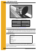
3. PRE INSTALLATION 18" & 24" Roof Fan Package Figure 3A An 18" Roof Exhaust Fan 18" Roof Fan Package Roof fan assembly Bottom mounting flange Hardware package Manual PNEG-524 24" Roof Fan Package Roof fan assembly Manual PNEG-524 Fan housing top plate Adaptor-top, right & left side Rain hood top, right & left side Hardware package (4) Template parts Your model package should contain items shown in above chart.
4. SPECIFICATIONS Fan Model Specifications for Roof Fans 24" Roof Exhauster Motor Specifications Exhauster Model Fan Subassembly Motor Part # HP Phase Voltage Enclosure RPM Full Load Amps TEFC 1725 11.5 MIS-6675-1 MIS-6674-1 MIS-6729 2 1 230 MIS-6675-3 MIS-6674-3 MIS-6686 2 3 208 - 230/460 TEFC 1740 6 - 5.6/2.8 MIS-6675-3E MIS-6674-3E MIS-6704 2 3 230/460 XPFC 1740 5.6/2.8 MIS-6675-5 MIS-6674-5 MIS-6800 2 3 575 TEFC 1740 2.
5. INSTALLATION Standard electrical safety practices and codes should be used when working with a fan. Refer to the National Electric Code Standard Handbook by the National Fire Protection Association. A qualified electrician should make all wiring installations.
5. INSTALLATION 18" Roof Fan Mounting The roof fan can be installed in the roof sheet before assembling the roof, or after the roof is assembled. Locate roof fan so that inner roof structure does not interfere with installation. The fan is secured by bolts that must be fastened from the inside of the bin roof, and therefore the assembly should be made before the side walls are erected. 1.
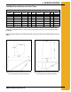
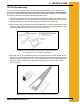
5. INSTALLATION 24" Roof Fan Mounting and Assembly of Fan, Adaptor and Rain Hood The roof fans, adaptor and rain hood can be installed in the bin roof sheet before assembling the roof or after the roof is assembled. The fan is secured by bolts that must be fastened from the inside of the bin roof, so the assembly should be made before the sidewalls are erected. 1. Assemble the roof sheet mounting template as shown in Figure 5C. Figure 5C 24" Roof Fan Template Placement on the Roof Sheet.
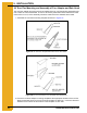
5. INSTALLATION 3. Drill two corner holes and bolt template in place. 4. Drill the remaining 11/32" mounting holes identified on the template. Figure 5E The Rainhood Preassembly. 5. Mark a cutting line 3/4" inside the template. Then remove template. Drill through the mark, cutting a hole in the roof sheet (See Figure 5F). 6. Preassemble the adaptor section parts of the roof fan. Loosely bolt the adaptor left side and right side to adaptor top.
5. INSTALLATION 9. Form a lip up around the inside of the adaptor opening by peening up the edge of the roof sheet extending past the inner edge of the roof adaptor. 10. Loosely bolt the rainhood top plate, rainhood right side and rainhood left side together. 11. Bolt the fan housing to the adaptor (See Figure 5H). Figure 5H The 24" Roof Fan Exhauster and Rainhood. 12. At this time the optional 90° deflector may be preassembled. 13. Bolt deflector assembly to MIS6674 sub-assembly for noise deflection.
5. INSTALLATION 24" Roof Exhauster Reinforcement Kit Figure 5J 1. Refer Page 11 for the 24" roof adaptor template and mounting, and the 30° Roof Manual PNEG-030 for the roof channel assembly. 2. Install the roof support channels in the ribs of the upper panel where the exhauster is to be mounted. 3. Install the template and cut exhauster parts as specified on Page 11. 4. Utilize the upper MIS-6811 and lower MIS-6805 reinforcement supports to support the exhauster.
NOTES 14 PNEG-524 Roof Exhaust Fan
6. PARTS LIST 18" Roof Exhauster Parts Figure 6A 18" Roof Exhauster Parts Breakdown. 18" Roof Exhauster Parts Ref # Part # Description Qty 1 F-942 Control box lid 1 2 FH-4429-1 Lid clamp 2 3 F-6864 Control box wrapper 1 4 MIS-6680 18" exhauster weldment 1 5 F-6701 Motor support bracket 1 6 F-953 Fan grill guard 1 7 MIS-6689 18" fan blade 1 8 MIS-6688 .5 H. P.
6.
6. PARTS LIST 24" Roof Exhauster Parts Ref # Part # Description Qty 1 MIS-6664 Adaptor top plate 1 2 MIS-6666 Exhauster adaptor left panel 1 3 MIS-6665 Exhauster adaptor right panel 1 4 MIS-6686 2 H. P.
7. ELECTRICAL INSTALLATION Electrical Installation of the Fan The electrical installation must be performed by a certified electrician in accordance with the appropriate national and local electrical codes. WARNING ANY VIOLATION OF ELECTRICAL WIRING CODES COULD JEOPARDIZE THE AIRSTREAM WARRANTY. Check the type of electrical service present, and make sure the fan to be wired is manufactured to operate on the electrical service.
7. ELECTRICAL INSTALLATION Fan Disconnect A disconnect for the fan needs to be sized to handle the recommended fusetron size. Example: For a 24" fan the first chart on Page 17 would be used, and the fusetron size is 30 AMP. Install the fusetron recommended in the disconnect. A circuit breaker can be used, however, the circuit breaker or any fuse used must be a time delay type to allow the initial starting inrush current to the fan.
7. ELECTRICAL INSTALLATION Three Phase System With the power OFF at the fan disconnect, exchange the location of the current carrying conductors at terminal L1 and L3 (See Figure 7A) of the magnetic controls. The unit will then need to be rechecked for proper rotation. Figure 7A Connecting the Fan Rotation for Three Phase. Always check current local, state and national codes on electrical requirements before installing any electrical equipment.
8. OPERATING INSTRUCTIONS Before Starting Fan When starting the fan for the first time, check the following: 1. With the power OFF, rotate the fan blade to make sure it revolves easily, and does not rub on the venturi or fan tube. 2. Check all the fasteners to make sure they are tight. If any are loose, check for proper clearance and retighten. 3. With the power OFF, check all electrical connections to make sure they are tight. Inspect the current carrying wires to make sure they are not grounded.
8. OPERATING INSTRUCTIONS If the fan just hums when turned ON, check the following: 1. Check to make sure that all leads of your power source have voltage present. If fan unit is not receiving power on all leads, check for a blown fuse, broken wire or loose connection. 2. Check to see that all contact sets are closing. If one leg of the supply voltage is not available to the motor it will hum. 3.
9. WARRANTY Warranty THE GSI GROUP, INC. (GSI) WARRANTS ALL PRODUCTS WHICH IT MANUFACTURES TO BE FREE OF DEFECTS IN MATERIAL AND WORKMANSHIP UNDER NORMAL USAGE AND CONDITIONS FOR A PERIOD OF 12 MONTHS AFTER RETAIL SALE TO THE ORIGINAL END USER. THE PURCHASER’S SOLE REMEDY AND GSI’S ONLY OBLIGATION SHALL BE TO REPAIR OR REPLACE, AT GSI’S OPTION AND EXPENSE, PRODUCTS THAT, IN GSI’S SOLE JUDGMENT, CONTAIN A MATERIAL DEFECT DUE TO MATERIALS OR WORKMANSHIP.
This equipment shall be installed in accordance with the current installation codes and applicable regulations which should be carefully followed in all cases. Authorities having jurisdiction should be consulted before installations are made. GSI Group, Inc. 1004 E. Illinois St. Assumption, IL 62510-0020 Phone: 1-217-226-4421 Fax: 1-217-226-4420 Internet: http://www.grainsystems.