00 Series Portable Dryer Parts Manual PNEG-545 Date: 09-22-10 PNEG-545
PNEG-545 100 Series Portable Dryer
Table of Contents Contents Chapter 1 Main Structure Assembly ................................................................................................................. 4 Frame Assembly ................................................................................................................................ 4 Frame, Auger Trough, Hopper Bulkheads and Metering Rolls .......................................................... 7 Plenum (Inside) Screens and Meter Roll Upper Shield ..................
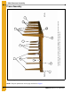
1. Main Structure Assembly The fan/heater end of the dryer is considered by GSI as the front end of the dryer (the foreground of this photograph is the front end. Right and left sides are labeled above). Right side 1 2 4 5 3 5 3 1a 5 3 4a 5 3 Left side Frame Assembly Figure 1A Frame Assembly (View from Fan/Heater End with Hitch Weldment Removed) NOTE: The parts pointed out on this page are listed on Page 6.
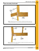
1. Main Structure Assembly Frame Assembly (Continued) 3 1 1a 4 2 4a NOTE: The right front corner is shown in the photo. For left front corner all parts are the same except for the hitch bracket (use 1a for the left side) and the frame rail (use 4a for the left side). Figure 1B Right Front Corner of Frame 3 5 2 4a 4 NOTE: The left rear corner is shown in the photo. For right rear corner all parts are the same except for the frame rail (use 4 for the right side).
1.
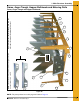
1. Main Structure Assembly Frame, Auger Trough, Hopper Bulkheads and Metering Rolls 8 11 5 9 4 7 6 9 5 4 10 6 3 2 1 NOTE: The hole pattern of the plenum closure door angles. This will distinguish between L.H. and R.H. Dryer frame and lower basket assembly (view from the front end of the dryer looking down the left side.) 6 Frame, Auger Trough and Hopper Bulkheads Figure 1E NOTE: The parts pointed out on this page are listed on Page 10.
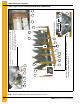
12 13 8 6 14 4 15 3 9 3 6 12 11a 5 12 9 6 3 6 20 19 Discharge bearing plate 4 Wooden meter roll support bearing. The meter roll sections are spliced together with a meter roll splice shaft (part # D31-0046) that passes through the support bearing assembly. Dryer frame and lower basket assembly (view from the rear end of the dryer looking up the right side.) 12 Center hanger bearing support and cross channel seal plate 16 21 17 9 18 1.
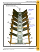
1. Main Structure Assembly Metering Rolls and their Placement in the Dryer NOTE: Ref # 22 at the rear of dryer is a front section meter roll that is used as a rear section on 16 and 20 foot dryers only. 22 24 Meter roll bearing Ref # 16,17 and 18 on page 10. 23 23 Meter roll bearing Ref # 16,17 and 18 on page 10. 23 23 Meter roll bearing Ref # 16,17 and 18 on page 10. 22 22 This end is the front (fan/heater) end of the dryer.
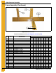
1. Main Structure Assembly Frame, Auger Trough, Hopper Bulkheads and Metering Rolls Parts List (See Figure 1E, 1F and 1G) REF # PART # DESCRIPTION QTY 108T 112 114 116 118 120 122 126 1 D01-1136Y PLENUM CLOSURE DOOR ANGLE, R.H. 3 5 6 7 8 9 10 12 2 D01-1136X PLENUM CLOSURE DOOR ANGLE, L.H.
1. Main Structure Assembly Plenum (Inside) Screens and Meter Roll Upper Shield Plenum (Inside) Screens and Plenum Closure Doors 3B 4 2 3A 1 5 5 6 16 7 8 7 10 11 13 14 15 18 9 19 20 12 10 This photograph was taken before the front plenum end panel and outer screens were installed in order to get a good view of the inside screens and bulkheads. 20a 21 Plenum closure door. There are two different plenum closure doors.
1.
1. Main Structure Assembly Outer Screens and Meter Roll Access Door Outer Screens 3a * 2 * 3 4 * 3 2 4 3 3a 1B 5 1A 9 10 6 14 12 7 13 8 9 10 11 See Figure 1K on Page 14 NOTE: Ref # 3 is pointing to the top edge angle gusset. There are two types of gusset on the dryer. The photo above will help distinguish the difference between the two. The arrows are pointing to a tab on the gusset that makes them different (tabs are “bent” up in photo).
1. Main Structure Assembly Meter Roll Access Door 15 16 17 19 18 20 Figure 1K Outer Screens and Meter Roll Access Door Parts List (See Figure 1J and 1K) REF # 14 PART # DESCRIPTION QTY 108T 112 114 116 118 120 122 126 1A D01-2466 COLUMN END PANEL FRONT RIGHT 1 1 1 1 1 1 1 1 1B D01-2467 COLUMN END PANEL FRONT LEFT 1 1 1 1 1 1 1 1 2 D01-0113 WALK RAIL MOUNTING BRACKET 10 16 18 20 22 24 28 32 3 D01-0152 TOP EDGE ANGLE GUSSET - L.H.
1. Main Structure Assembly Clean-Out Doors 1 11 3 13 9 2 4 5 Front and rear handle mechanisms (rear shown in photo) 4 3 5 3a 11 2 6 7 10 Clean-out door handle mechanism 11 10 NOTE: Ref # 9, 10 and 11 together create the clean-out door assembly. There are three different clean-out door assemblies that are used on GSI Network dryers: 1) 3-column clean-out door assembly (D51-0077). Ref # 8a on the part # listing (Page 16). 2) 4-column clean-out door assembly (D11-0032).
1.
1.
1.
1. Main Structure Assembly Ladder and Step Assemblies Fan Access Step 6 5 7 8 1 2 3 4 Figure 1P Fan Access Step Parts List REF # PART # QTY DESCRIPTION 108T 112 114 1 1 1 116 118 120 122 126 1 1 1 1 1 2 2 2 2 1-4 D01-1198 FAN ACCESS STEP KIT 1 D01-1168 FAN ACCESS STEP L.H. MOUNT 1/KIT 2 D01-1166 FAN ACCESS STEP 1/KIT 3 D51-0022 SUPPORT, CONTROL PANEL 1/KIT 4 D01-1167 FAN ACCESS STEP R.H. MOUNT 1/KIT 5 SEE REF # 5 ON PAGE 20. 6 SEE REF # 6 ON PAGE 20.
1.
1. Main Structure Assembly Bottom Auger 1 2 2 3 2 4 Bottom auger (view from center of dryer to the rear end.) Bottom auger (view from center of dryer to the forward end.
1.
1.
1.
1. Main Structure Assembly Top Auger with Wet Bin Assembly Parts List (See Figure 1T and 1U) REF # PART # 1 D01-1521 DESCRIPTION WET BIN SIDE, 4' SIDE GALV. PERF 1 D01-1522 WET BIN SIDE, 6' SIDE GALV. PERF 2 D01-0103 MERCURY SWITCH SHAFT 3 D21-0003 TOP EDGE ANGLE 71.875" 3 D31-0004 TOP EDGE ANGLE 95.875" 3 D01-0168 TOP EDGE ANGLE 119.
2.
2. Auger and Meter Roll Drive Trains Bottom Auger Drive (Continued) 21 22 19 20 Figure 2B Bottom Auger and Metering Roll Drive Guard REF # PART # DESCRIPTION 1 D01-1376 BOTTOM FRONT ANGLE BRACKET 2 D02-0067 BELT - V BX85 2 MHC00490 BELT - V BX82 3 D03-0174 SHEAVE 2.5 D x 7/8" BORE 3 2818-2 SHEAVE 2 GR 3.35 D x 1-1/8" 3 D62-0003 SHEAVE 2 GR 4.
2.
2. Auger and Meter Roll Drive Trains Top Auger Drive (Continued) 7 8 9 10 11 Figure 2D Top Auger Motor and Motor Mount Top Auger Drive Parts List (See Figure 2C and 2D) REF # PART # DESCRIPTION QTY 108T 112 114 116 118 119 122 126 TOP AUGER BELTGUARD BODY 1 1 1 1 1 1 1 1 D52-0001 SHEAVE 2 GR 16" GRIPBELT 1 1 1 1 1 1 1 1 D32-0019 BUSHING Q1 - 1-1/2" SPLIT TAPER 1 1 1 1 1 1 1 1 D01-0464 BELT-V BX97 2 2 2 2 2 2 2 2 D03-0174 SHEAVE 2.
2.
2.
3.
3.
3. Fan/Heaters Fan Motor, Motor Mount and Fan Blade 1 2 4 3 Fan motor and motor mount Fan blade and bushing Figure 3C Fan Motor, Motor Mount and Fan Blade Parts List FAN/ HEATER (DIA.
3.
3. Fan/Heaters Flame Probe, Ignitor and Burner Assemblies 8 1 9 10 Ref # 9 and 10 are used in LP fan/heaters only.
3.
3.
3.
3.
3.
3.
3.
3.
3.
3.
4.
4. Dryer Electrical Conduits Right and Left Grain, and Plenum High-Limits (Continued) 8 Grain temperature thermistor. There are 2 thermistors in each (right and left) grain high-limit thermostat assemblies.
4. Dryer Electrical Conduits Lower Junction Box, Meter Roll Motor Conduit and Rear Discharge Conduit 3 8 4 9 5 6 6 2 5 7 1 2 1 2 3 Conduit to meter roll motor (see photo below) 4 1 Lower junction box (right) 8 10 Lower junction box (left) Conduit to meter roll speed sensor and rear discharge switch (See photos below and on next page). 1 11 Meter roll motor conduit connection 14 13 Rear discharge switch conduit at rear left gusset where 1/2" EMT conduit terminates.
4.
4. Dryer Electrical Conduits Upper Junction Box, Top Auger Motor Conduit and Operator Light 1 11 4 3 5 6 Top auger motor conduit 2 12 9 9 10 10 1 2 Upper junction box 15 11 Fill switch assembly (installed) 7 1 13 14 2 9 8 Fill switch assembly (opened) Operator light Ref # 9-15 are components of the fill switch box assembly (fill switch assembly) part # D01-0192.
4. Dryer Electrical Conduits Upper Junction Box, Top Auger Motor Conduit and Operator Light Parts List (See Figure 4E) REF # 52 PART # DESCRIPTION 1 D03-0057 CONDUIT 1/2" EMT METALLIC 2 D03-0054 CONNECTOR 1/2" EMT COMPRESSION 3 HH-1096 CLAMP 1/2" CONDUIT 4 D03-0075 CONNECTOR 1/2" EMT TO SEALTITE 5 120-1538-4 SEALTITE PVC 1/2" 6 006-1377-1 ELBOW 1/2" 90° PVC WITH 7 D03-0117 LAMP 90° W/JUNC. BOX 8 D03-0575 BULB, 100W 130V ROUGH SERVICE 9 FH-6972 ENCLOSURE 4 x 4 x 2.
4. Dryer Electrical Conduits Air Switch Assembly 3 4 7 9 8 2 5 6 Air switch assembly (internal parts) 10 10 11 11 1 Air switch assembly (P/N D01-0672) 1-9 Upper air switch assembly (installed) Figure 4F Air Switch Assembly Parts List REF # PART # DESCRIPTION QTY 1-9 D01-0672 AIR SWITCH ASSEMBLY 1 D01-0671 AIR SWITCH BOX CONDUIT HALF 2/ASSEMBLY 2 D01-0670 AIR SWITCH BOX FACE PLATE 1/ASSEMBLY 3 DC-1103 DECAL, AIR PRESSURE ADJUSTMENT 1/ASSEMBLY 4 D03-0177 GROMMET, 11/16" I.D.
5. Control Boxes Fan/Heater Electrical Box Starter capacitor circuit used on single phase 220 volt only. Starter capacitor circuit is supplied with motor. 1 2 3 4 5 6 7 8 9 Figure 5A Fan/Heater Control Box Fan/Heater Electrical Box Parts List REF # 54 PART # DESCRIPTION ALL FAN/HEATERS 1 045-1016-0 TERMINAL STRIP ASSEMBLY 75A 3 POS 1 2 401-5283-7 CTRL BOX - BASE - GALV.
5.
5.
5.
5.
5.
5.
5.
5.
5.
5.
5.
5.
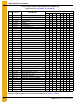
5. Control Boxes Auxiliary Motor Circuits This chart shows the part numbers for circuit breakers, contactors, and overload relays used in various sized motor branch circuits. Find the rows that corresponds to the size of your auxiliary motor then follow the row that corresponds to the phase and voltage of your dryer to find the part numbers for the components in that motor branch circuit. Phase & Voltage 3 HP Motor Branch Circuits 5 HP Motor Branch Circuits 7.
NOTES 68 PNEG-545 100 Series Portable Dryer
6. Warranty GSI Group, LLC Limited Warranty The GSI Group, LLC (“GSI”) warrants products which it manufactures to be free of defects in materials and workmanship under normal usage and conditions for a period of 12 months after sale to the original end-user or if a foreign sale, 14 months from arrival at port of discharge, whichever is earlier.
This equipment shall be installed in accordance with the current installation codes and applicable regulations which should be carefully followed in all cases. Authorities having jurisdiction should be consulted before installations are made. GSI Group 1004 E. Illinois St. Assumption, IL 62510-0020 Phone: 1-217-226-4421 Fax: 1-217-226-4420 www.gsiag.