GSI Competitor & EMCS Portable Dryer Models Troubleshooting and Reference Manual 2004 Revised Edition PNEG-630 Competitor Series 2000 Dryer
Portable Dryer Troubleshooting Table Of Contents Safety ..................................................................................................................................................................... 3 Safety Sign Off Sheet ............................................................................................................................................ 8 EMCS Portable Dryer (1993-1998) Safety Voltage Check Points .............................................................
Table Of Contents Portable Dryer Troubleshooting Competitor Series 2000 Dryer (Picture of Dryer)(1995 to Present)......................................................65 220 Volt Single (1) Phase Power Drawing ............................................................................................................ 66 220 Volt Single (1) Phase Power Drawing (New Version) .................................................................................. 67 220 Volt Three (3) Phase Power Drawing .........
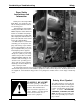
Portable Dryer Troubleshooting Safety Dryer Safety Instructions and Information Thank you for choosing an GSI Grain Dryer. It is designed to provide excellent performance and service for many years. This manual refers to the troubleshooting of the E.M.C.S.and Series 2000 Competitor models. Different models are available for liquid propane or natural gas fuel supply, with either single phase 230 volt, or three phase 230, 460, 575 volt electrical power. (Also 380 volt 50Hz). The GSI Group Inc.
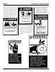
Safety Portable Dryer Troubleshooting Grain Systems, Inc. recommends you contact your local power company and have a representative survey your dryer installation, so your wiring will be compatible with their system and you will have adequate power supplied to your unit. A CAREFUL OPERATOR IS THE BEST INSURANCE AGAINST AN ACCIDENT Safety decals should be read and understood by all people in and around the dryer area.
Portable Dryer Troubleshooting Safety 5
Safety 6 Portable Dryer Troubleshooting
Portable Dryer Troubleshooting READ THESE INSTRUCTIONS BEFORE OPERATION AND SERVICE SAVE FOR FUTURE REFERENCE 1. Read and understand the operating manual before trying to operate the dryer. 2. 3. 4. 5. 6. Safety Precautions Use Caution in the Operation of this Equipment The design and manufacture of this Power supply should be OFF for service of electrical components. Use dryer is directed toward operator CAUTION in checking voltage or other procedures requiring power to safety.
Safety Sign-Off Sheet Date Portable Dryer Troubleshooting Employer’s Signature Employee ________________________________________________________________________________________________________________________ _________________________________________________________________________________________________________________________ ________________________________________________________________________________________________________________ _______________________________________________________________
Misc Errors Auxilliary Safety Shutdown Motor Overload Grain Discharge Warning Maxon Valve Shut Warning Unknown Safety Error 20 Second Safety Circuit Failure Lower or Left Fixed Grain Lower Adjustable or Right Fixed Grain Middle Fixed Grain Middle Adjustable Grain Upper Fixed Grain Upper Adjustable Grain + J1-7 J1-5 J1-9 J1-11 J1-13 J1-13 J1-13 J5-12 J5-12 J5-12 J5-12 J5-12 J5-12 J1-20 J4-12 J5-5 J5-2 J5-10 J5-6 1100/1200/1300 J5-12 J1-19 J5-12 J4-19 J5-12 N/A J5-12 N/A J5-12 N/A J5-12 N/A 1 J5-12 J5-1
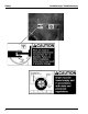
Programming Portable Dryer Troubleshooting Programming Instructions for EMCS Grain Dryers 1. Turn Control Power on dryer to off. 2. Locate programming jack (P7) on back of computer. (See page 13). 3. Plug the DB-9 jack of the programmer into the computer's jack. 4. Be sure that the rotary switch on the programmer is set to position 8. 5. Turn on Control Power to the dryer. 6. The four (4) lights on the programmer will come on, then three (3) will go out leaving the power light still on. 7.
DISPLAY RIBBON P1 TO START & STOP SWS. U12 1 2 3 P6 P3 TO START SW. BATTERY (TIC) P8 COMMUNICATIONS CABLE TO I/O BOARD P4 P5 S1 SOUND TO STOP SW.
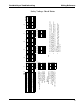
Portable Dryer Troubleshooting Wiring Reference Input/Output Board Identification 12 VOLT DC INPUTS +12 LIMIT OUTPUT 20 19 120VAC POWER (INPUT) 1 2 120VAC POWER (OUTPUT) 12 VOLT DC NEUTRAL 18 17 +12 LIMIT OUTPUT AC NEUTRAL 3 4 AC NEUTRAL METERING ROLL INPUT 16 15 12 VOLT DC NEGATIVE 120VAC POWER (INPUT) 5 6 120VAC POWER (OUTPUT) 12 VOLT DC NEGATIVE 14 13 12 VOLT DC NEGATIVE AC NEUTRAL 7 8 AC NEUTRAL 12 VOLT DC NEGATIVE 12 11 12 VOLT DC NEGATIVE AC NEUTRAL 9 10 AC NEU
Switch Replacement Portable Dryer Troubleshooting Switch Replacement for EMCS Dryer Switch N/O Contact Block - Part No.
Portable Dryer Troubleshooting Wiring Reference 1100 Series Control Box Wiring 1100 FAN TO CONTROL BOX WIRING DESCRIPTION AIR PRESSURE SWITCH +12VDC VAPOR HIGH LIMIT (LP ONLY) RELAY CONTACTS LOCATED IN DRYER FAN CAN BOX RED J5-8 12 VOLTS DC (RED) YEL J1-7 12 VOLTS DC (RED) PUR J1-5 12 VOLTS DC (RED) (RED) YEL FLAME DETECTION PLENUM J1-9 12 VOLTS DC BLU J1-11 12 VOLTS DC (RED) OR J1-19 12 VOLTS DC (RED) OR J5-5 12 VOLTS DC (RED) OR J4-19 OR RED LEFT FIXED GRAIN HI LIMIT B
Portable Dryer Troubleshooting Wiring Reference 1100 Series Control Box Wiring (New Version) 15
Portable Dryer Troubleshooting Wiring Reference 1200 Series Control Box Wiring 52 TOTAL TERMINALS DESCRIPTION WIRING AIR PRESSURE SWITCH +12VDC NEED JUMPER OR FAN #2 HOUSING HIGH LIMIT FAN #2 VAPOR HIGH LIMIT SAFETY CIRCUIT RELAY CONTACTS LOCATED IN FAN CAN CONTROL BOX RED FAN #2 FLAME DETECTION FAN #1 HOUSING HIGH LIMIT OR TERMINAL RED FAN #1 FLAME DETECTION FAN #2 PLENUM FAN #1 PLENUM FIXED GRAIN HIGH LIMIT RED *REAR DISCHARGE BRN ADJ.
Portable Dryer Troubleshooting Wiring Reference 1200 Series Control Box Wiring (New Version) 17
Wiring Reference Portable Dryer Troubleshooting 1100 Fan Lower Control Box Interconnect Strip J9-1 18 5VB1 35 - D01-0531 ENTRELEC TERMINALS 2 - D01-0533 END STOPS 1 - D01-0532 BLANK PROTECTOR END LINE L1 B1 S1 S2 SCR2 J1-5 J1-7 J1-9 J1-11 J1-13 J1-19 J1-20 J4-12 J4-19 J5-4 J5-5 J5-8 J5-9 J5-12 J5-16 J5-19 J6-1 J6-4 J7-3 J7-4 J7-8 J8-8 J8-9 J8-10 J8-12 J8-16 J8-18 J8-20 J9-16 J9-17 LOAD EMERGENCY COOLING JUMPERS INSTALL J6-13 TO J1-5 INSTALL J6-14 TO J1-19 INSTALL J6-16 TO J5-5 INSTALL J6-17 TO J4-1
Wiring Reference Portable Dryer Troubleshooting 1200 Fan Lower Control Box Interconnect Strip J9-1 AC-1 LINE LOAD 5VB1 J9-3 J9-3 EMI FILTER D03-0181 BLACK - 120 VAC - OUTSIDE LIGHT BROWN - 120 VAC - BURNER #1 LIGHT BROWN - 120 VAC - BURNER #2 LIGHT ORANGE - TEMPERATURE SENSOR ORANGE - TEMPERATURE SENSOR PURPLE - CONTROL POT P2 RED - 12 VDC - FAN #1 VAPOR HIGH LIMIT RED - 12 VDC - FAN #2 VAPOR HIGH LIMIT RED - 12 VDC - FAN #1 HOUSING HIGH LIMIT RED - 12 VDC - FAN #2 HOUSING HIGH LIMIT RED - 12 VDC
Portable Dryer Troubleshooting Wiring Reference Upper Control Box External Wiring BLACK FROM J9-16 TO L1 ON FENWAL BOARD 120VAC POWER WHITE FROM J7-04 TO L2 ON FENWAL BOARD 120VAC NEUTRAL BROWN TO B1 FROM V1 ON FENWAL BOARD 120VAC ORANGE FROM J1-09 TO FLAME DETECTION RELAYS ORANGE FROM J5-08 TO FLAME DETECTION RELAYS TO FAN CONTROL BOX WHITE/BLACK STRIP J5-12 12VDC NEGATIVE YELLOW TO J1-07 FROM HOUSING HIGH LIMIT SWITCH RED FROM J5-08 TO HOUSING & VAPOR HIGH LIMIT SWITCHES PURPLE TO J1-05 FROM VAPOR HI
Portable Dryer Troubleshooting Wiring Reference Fan Housing and Vapor Hi-Limit Circuit 21
Wiring Reference Portable Dryer Troubleshooting Plenum Hi-Temperature Switch 22
Portable Dryer Troubleshooting Wiring Reference Fixed Grain Hi-Limit 23
24 BLUE J1-11 RED J5-05 ORANGE J4-19 YELLOW J1-05 TO UPPER CONTROL BOX BLUE J1-11 LEFT GRAIN HIGH LIMIT SWITCH D03-0005 210 DEGREE YELLOW J1-05 RIGHT GRAIN HIGH LIMIT SWITCH D03-0005 210 DEGREE RED J1-11 ORANGE J1-19 TO LOWER JUNCTION BOX PLENUM HIGH LIMIT SWITCH D03-0004 300 DEGREE AIR SWITCH UNLOAD MOTOR LOWER JUNCTION BOX SCR GAS PIPE TRAIN TEMP. SENSORS TEMP.
FAN #1 PLENUM HIGH LIMIT SWITCH D03-0004 300 DEGREE FIXED GRAIN HIGH LIMIT SWITCH D03-0005 210 DEGREE FAN #2 PLENUM HIGH LIMIT SWITCH D03-0004 300 DEGREE RED TO J1-11 ORANGE TO J1-19 TO LOWER JUNCTION BOX ADJUSTABLE GRAIN HIGH LIMIT TEMP. SENSORS OUTSIDE LIGHT LOAD MERCURY SWITCH FAN #1 FAN #2 12XX SOLENOID AIR SWITCHES SOLENOID SCR BURNER #1 HI-LOW THERMO BURNER #2 HI-LOW THERMO MAXON 2FNLMTSW98.PRT REV.
Wiring Reference Portable Dryer Troubleshooting Rear Discharge & Emergency Cooling Circuit 26
LOOSEN SCREWS ON BRACKET TO CHANGE SENSITIVITY OF REAR DISCHARGE SWITCH CONNECT TO SJOW CORD INSIDE LRL BOX POSITIONED WITH LID CLOSED AND SJOW 18/2 CORD POINTED TOWARDS THE FRONT OF THE DRYER CONNECT INSIDE METER ROLL BOX TO BROWN AND ORANGE WIRES.
Wiring Reference Portable Dryer Troubleshooting Adjustable Hi-Limit & Emergency Cooling Circuit 28
Portable Dryer Troubleshooting Wiring Reference Motor Overloads 29
Portable Dryer Troubleshooting Wiring Reference Air Pressure Switch J5 11 12 VOLT SOURCE 12 VOLT DC NEGATIVE 8 DC POSITIVE J5-8 J1-8 J1-6 J1-10 12 J1-7 J4 J1-5 J1-9 J1-12 J1-11 J1-19 12V DC SOURCE FROM MOTOR OVERLOADS J3 J6-14 J5-5 J4-19 J6-17 BLUE J4-12 FAN #2 PRESSURE SWITCH BLUE J1-14 FAN #1 PRESSURE SWITCH J1-13 BLUE J2 BLUE PRESSURE SWITCH SAFETY CIRCUIT 30 1413 J1 INPUT/OUTPUT BOARD TERMINAL LOCATIONS
HIGH C N.C. N.O. CALIBRATED WITH DIAPHRAGM VERTICAL TO UPPER CONTROL BOX BLUE J1-13 AIRFLOW (N.O.) BLUE J5-08 12VDC POSITIVE BACKVIEW OF AIR SWITCH ASSEMBLY AIR SWITCH UNLOAD MOTOR LOWER JUNCTION BOX SCR GAS PIPE TRAIN TEMP. SENSORS TEMP.
Wiring Reference Portable Dryer Troubleshooting Out of Grain Safety Circuit 32
UP REMOVE THESE EARS SJOW 18/2 WIRE EXITS THROUGH BOX COVER WHITE BLACK FRONT VIEW OF OPEN BOX LEADS MUST BE IN THIS POSITION FOR PROPER OPERATION FAN AIR SWITCH UNLOAD MOTOR LOWER JUNCTION BOX SCR GAS PIPE TRAIN TEMP. SENSORS TEMP.
34 BLACK WHITE BLACK WHITE J9-03 BLACK BLACK L1 TO 12VDC J5-09 J5-04 TO UPPER CONTROL BOX TO OUTSIDE LIGHT FIXTURE RED WHITE TO LOAD MERCURY SWITCH AIR SWITCH UNLOAD MOTOR LOWER JUNCTION BOX SCR GAS PIPE TRAIN TEMP. SENSORS TEMP.
TO REAR JUNCTION BOX LEFT METER ROLL SENSOR 16 J519 05 J1J5- Y B ELL RE LACK OW D RED 12VDC POS BLACK OR WHITE/BLACK STRIP 12VDC NEG YELLOW LEFT METER PULSE RETURN BLUE RIGHT METER PULSE RETURN ORANGE REAR DISCHARGE RETURN BROWN 12VDC TO DISCHARGE SWITCH OR BR ANGE OW N 2 5-1 9 J 5J -0 19 J5- D RE K LB AC E U BL RIGHT METER ROLL SENSOR TO REAR DISCHARGE SWITCH J509 J512 J519 NOTE: RIGHT SENSOR IS NO LONGER USED ON DRYERS MANUFACTURED AFTER MARCH 1, 1997 Portable Dryer Troubleshooting Wiring Refe
T-3 T-2 T-1 12 Volt - T-3 T-2 T-1 1997 Dryers have only 1 meter roll board. Remove one meter roll board and tie the 2 T-3 wires together.
Wiring Reference Portable Dryer Troubleshooting Meter Roll Reversing YOU MUST ENTER INTO THE DRYER PARMETER MODE BY PRESSING THE INCREASE AND DECREASE BUTTONS SIMULTANIOUSLY. YOU WILL HAVE THE FOLLOWING OPTIONS LISTED: SHUTDOWN HISTORY (PRESS ENTER) DRYER MODEL # (IE. 1112) FAN DELAY (DEFAULT = 5) FILL AUGER (DEFAULT = END) BPH FACTOR (DEFAULT = 1.0) TEST METER ROLL (DEFAULT = YES) TEST AIR SWITCH (DEFAULT = YES) M.R.
WIRES GO TO UPPER CONTROL BOX 38 WHITE J7-08 RED 16 GA. A+ TO SCR DRIVE MOTOR BLACK 16 GA. A- TO SCR DRIVE MOTOR GREEN 16 GA.
Portable Dryer Troubleshooting Wiring Reference New Fenwal Board Wiring The B. GND terminal is used to ground the burner and to complete the flame current signal circuit. This terminal is new for systems that used the older version of the Fenwal board. This terminal must be connected to the burner (chassis) ground not only to ensure the best, long term, stable flame signal, but also to ground the burner for proper sparking.
Portable Dryer Troubleshooting Wiring Reference Fenwal Board Troubleshooting On-Board Diagnostics The LED will flash on for 0.2 seconds then off for 0.2 seconds to indicate an error condition. The pause time between error codes will be 2.5 to 3.0 seconds. During power-up, the LED will light for one second and then turn off to indicate normal operation.
OR OR ALL WIRES COME FROM MAIN CONTROL BOX 20 SEC SAFETY 20 SEC INPUT 12 VOLTS DC WHT BLK BRN 120 VOLTS AC NEUTRAL 120 VOLTS AC BURNER LIGHT S1 L1 BLK BRN WHT V2 FENWAL BOARD V1 E2 WHT L2 Neutral TIME DELAY WHT Coil BLK WHT Neutral Coil BRN WHT BRN OR OR Normal Closed BLK Normal Closed COIL WHT WHT 1 3 2 5 4 6 8 7 OR OR TER. 1-5 (12 VOLTS DC) TER.
42 COM SWITCH CLOSES WHEN PRESSURE IS SENSED BROWN MERCOID PRESSURE SWITCH NEUTRAL- - - - WHT BURNER LIGHT - BRN 110 VOLTS AC 110 VOLTS AC TO BURNER CIRCUIT N/C N/O BRN V1 E1 S1 BLK L1 BLACK BROWN GREY V2 WHITE L2 FLAME SENSOR FENWAL PART# HF-4624 E2 IGNITOR WHITE PUR RED YEL ORG ORG PNK VAPOR LIMIT HOUSING LIMIT 12 VOLTS DC 20 SEC SAFETY 20 SEC INPUT MERCOID SAFETY WHITE BLK L1 BURNER TIME DELAY GREY 1 3 2 5 4 BLACK 7 6 ORG BLK WHITE ORG PURPLE PURPLE BROWN WHITE
Portable Dryer Troubleshooting Wiring Reference Conversion Diagram For C Series Dryers To A Switchable Hi/Low Burner Or A On/Off Burner 43
Wiring Reference Portable Dryer Troubleshooting Fan 28 LP Hi/Low-On/Off 44
Portable Dryer Troubleshooting Wiring Reference Fan 28 LP Hi/Low-On/Off Burner With Mercoid 45
Wiring Reference Portable Dryer Troubleshooting Fan 28 NG Hi/Low-On/Off 46
Portable Dryer Troubleshooting Wiring Reference Fan 28 NG Hi/Low-On/Off Burner With Mercoid 47
Wiring Reference Portable Dryer Troubleshooting Fan 42 LP Hi/Low-On/Off 48
Portable Dryer Troubleshooting Wiring Reference Fan 42 LP Hi/Low-On/Off Burner With Mercoid 49
Wiring Reference Portable Dryer Troubleshooting Fan 42 NG Hi/Low-On/Off 50
Portable Dryer Troubleshooting Wiring Reference Fan 42 NG Hi/Low-On/Off Burner With Mercoid 51
52 J6-4 SCR P3 W PUR OR P P P OR TO TERMINAL ON UPPER POWER STRIP WITH POWER WIRES A- A+ J6-1 SCR 2 SCR P2 J8-10 SCR POWER SCR P1 J8-20 SCR NEUTRAL To SCR Drive Motor L1 L2 6 8 A2 5 7 A1 COIL 2 3 F+ F- L1 L2 A+ A- OR T1 T2 S C R Board BLK BLK To Coil 220 Volt SCR CONTACTOR Fuse L2 L1 Wiring Reference Portable Dryer Troubleshooting SCR Drive Circuit 1
INSIDE GRAIN COLUMN CONDUIT FRONT WHITE 20 GA. BLACK 20 GA. WHITE 20 GA. BLACK 20 GA. TO UPPER CONTROL BOX WHITE S1 SOLDERED AND INSULATED INSIDE CONDUIT INSIDE GRAIN COLUMN CONDUIT FRONT BLACK S2 REAR REAR SOLDERED AND INSULATED INSIDE CONDUIT BLACK S2 WHITE S1 TO LOWER JUNCTIONL BOX AIR SWITCH UNLOAD MOTOR LOWER JUNCTION BOX SCR GAS PIPE TRAIN TEMP. SENSORS TEMP.
54 S2 3.4 ON 20K SCALE AT 70 DEGREES S1 1 2 3 7 8 9 MOISTURE CONTROL THERMOSTAT 6 5 4 J5-3 FIG.1 IF NONE OF THE MEASUREMENTS = 3.4 K, THEN CHECK EACH INDIVIDUAL SENSOR. IF MEASUREMENTS DO NOT = 3.4 K CHECK CONNECTIONS IN WHITE JUNCTION BOX ON FAR LEFT AND RIGHT SIDES FACING THE FAN END. IF OHMS DOES NOT = 3.4 K CHECK LOWER AND UPPER TERMINAL STRIP (ON SINGLE MODULES CHECK S1 & S2) (ON DOUBLE OR TRIPLE MODULES CHECK J6-9 TO J6-6 = 3.4 AND CHECK J6-11 TO J6-8 = 3.
Portable Dryer Troubleshooting Temperature Charts We use two (2) different types of sensors (NTC thermistor on the Competitor Series 2000, and an encapsulated sensor on the E.M.C.S dryer) in our dryers. The resistance of the sensors varies according to the outside temperature. For example, on the E.M.C.S. dryers, for every one (1) degree rise in temperature the resistance increases 4.8 ohms.
Troubleshooting Tips Portable Dryer Troubleshooting DC Drive Metering Roll System in the 2 Speed position. If this is present then the SCR contactor and input/output board are okay. Symptoms: Metering Roll will not turn, dryer shutdown-"Metering Roll Drive Failure" Metering Roll Operation • The DC drive system on the portable dryer is used to control the output of grain from the dryer. It is adjusted from the front of the control box using the high and low metering roll potentiometers.
Portable Dryer Troubleshooting Troubleshooting Tips Fenwal Ignition System. If no voltage is present after the 10 second purge delay, check for voltage going through the auxiliary switch mounted on the side of the fan contactor for that burner. This switch has to close before the Fenwal gets power. If this is OK, check the appropriate output on the input/output board for that burner.
Troubleshooting Tips Portable Dryer Troubleshooting Fenwal Ignition System continued... Hints • Hearing the solenoids snap on after the 10 second purge delay means that power is coming to and through the Fenwal board. The Fenwal board is probably okay. • If flame is sensed, the power to the solenoids stays on but the power to the ignitor always goes off after about four(4) seconds. • Power to the low pressure solenoid is always on anytime flame is sensed.
Troubleshooting Tips Portable Dryer Troubleshooting the incoming 12 volts DC (the T1-+12V and T2-GND terminals), and one is a pulsing 12 volts DC back to the input/output board (the T3 out terminal). Checking across T1 and T2 will verify that 12 volts DC is getting to the sensor.
Troubleshooting Tips Portable Dryer Troubleshooting driver and turn the adjusting screw counterclockwise. Turning it this way makes the switch more sensitive to pressure and will turn on the light easier. Air Pressure System • When inspecting the sensor make sure that the wheel going through the sensor is positioned in the center and is not touching either side. If the sensor is scratched it is either bad or will probably go bad.
Troubleshooting Tips Portable Dryer Troubleshooting • If all the above fails to work then remove the two wires while blowing into the air tube. Blowing into the switch is the same as having air pressure in the plenum. You should have an open circuit until you blow into the switch, then it should close. If the switch does not close try adjusting it, or replace it with a known good one. Vapor High Temperature Symptoms: Dryer runs for only a short period of time, then a shutdown occurs.
Troubleshooting Tips Portable Dryer Troubleshooting soon as the burner is turned on. The vaporizer must be adjusted to solve this problem. The two wrap has less surface area and it will not heat the LP quite as much. This may also be true in colder climates where a two wrap will not heat up enough. In this case, the pipe train may develop frost or even freeze the solenoids open.
Troubleshooting Tips Portable Dryer Troubleshooting Out Of Grain Warning Shutdown 2. Before setting the Out of Grain timer, monitor how long it takes the dryer to refill for shrink. Then, set the Out of Grain timer accordingly. Example: If a dryer takes six minutes to refill for shrink, add an additional five minutes to this, and use this as the amount of time to program into the Out of Grain timer. The additional five minutes is to avoid any nuisance shutdowns.
Troubleshooting Tips Portable Dryer Troubleshooting Motor Overload Helpful Hints Motor Overload Shutdown This indicates that one of the Motor Overloads has tripped, shutting down the dryer. Each of the Motor Overloads is located in the upper main power control box. They are all wired into a single series circuit that goes to the input/output board on terminal J4-12. Before the dryer will start terminal J4-12 must have 12 volts DC present, or the Motor Overload shutdown will occur.
Portable Dryer Troubleshooting Competitor Series 2000 Portable 65
5 6 7 8 9 10 TO LOAD MOTOR TO FAN #1 MOTOR AC-1 IR SCR BOARD RESISTOR 25 AMP 8 AMP 1F0 3FO SCR BOARD RESISTOR VALUES 1108-1112 (1/3H.P. 240V) #D03-0039 1114-1126 (3/4H.P.
Portable Dryer Troubleshooting Competitor Wiring Reference 220 Volt Single (1) Phase Power Drawing (New Version) 67
68 UNLOAD OVERLOAD 4 5 6 TO UNLOAD MOTOR 1 2 3 TO AUX UNLOAD MOTOR 10 11 12 TO LOAD MOTOR 7 8 9 TO AUX LOAD MOTOR LOAD AUX OVERLOAD LOAD CONTACTOR UNLOAD CONTACTOR UNLOAD AUX OVERLOAD LOAD BREAKER BREAKER UNLOAD LOAD OVERLOAD TO FAN #1 MOTOR 13 14 15 FAN #1 OVERLOAD FAN #1 CONTACTOR FAN 1 BREAKER AC NEUTRAL TRANSFORMER 110 VAC OUTPUT 220 VAC INPUT DISTRIBUTION BLOCK AC1 AC-1 3FO 110X0 1FO SCR CONTACTOR 120V FUSES 220V FUSES MAIN BREAKER Competitor Wiring Reference Portable
Portable Dryer Troubleshooting Competitor Wiring Reference 220 Volt Three (3) Phase Power Drawing (New Version) 69
Competitor Wiring Reference Portable Dryer Troubleshooting COMPETITOR POWER CIRCUIT ( 220 VOLT 1PH ) 70
Portable Dryer Troubleshooting Competitor Wiring Reference COMPETITOR POWER CIRCUIT ( 220 VOLT 3PH ) 71
Competitor Wiring Reference Portable Dryer Troubleshooting COMPETITOR POWER CIRCUIT ( 440 VOLT 3PH ) 72
Competitor Wiring Reference Portable Dryer Troubleshooting Upper Control Box Internal Wiring COM J3-02 COM YEL YEL R LOAD R WHT UNLOAD J3-01 UNLOAD UNLOAD OVERLOAD UNLOAD AUX. R R OR N/O N/C BREAKER R BREAKER ORG ORG R R R YEL N/O N/C J3-11 FAN #1 BREAKER LOAD LOAD OVERLOAD LOAD AUX.
Competitor Wiring Reference Portable Dryer Troubleshooting Series 2000 Control Box Wiring (New Version) 74
Portable Dryer Troubleshooting Competitor Wiring Reference Upper Control Box Wiring 220 Volt 1PH 75
Competitor Wiring Reference Portable Dryer Troubleshooting Upper Control Box Wiring 380, 460 & 575 3PH 76
Portable Dryer Troubleshooting Competitor Wiring Reference Series 100 Control Box Wiring 1 - END PROTECTOR# D01-0532 48 - COMPRESSION TERM.
Competitor Wiring Reference Portable Dryer Troubleshooting Upper Terminal Strip With Moisture Control Hook Up 78
Portable Dryer Troubleshooting Competitor Wiring Reference Upper Terminal Strip With Moisture Control Relay Hook Up 79
Competitor Wiring Reference Portable Dryer Troubleshooting Moisture Manager to Dryer Wiring (Upper Control Box) 80
2 20 BLK J1 J4 19 YEL 1 RED-2 ORANGE-1 WHITE-5 YELLOW-1 BLACK-1 PURPLE-2 2 WIRES TO DOOR: BLUE-3 BLACK-4 WHITE-6 RED-6 YELLOW-1 ORANGE-2 GREY-1 WHT/BLK-2 ORG PUR PUR RED 20 3 AMP FUSE RED PNK RED J6-02 EMI FILTER D03-0181 LOAD TO I/O BOARD: WHT WHT WHT WHT WHT LINE 5VB1 CORCOM AC1 RED --- J1-13 PNK --- J1-16 - - CANADIAN MODELS ONLY RED --- J1-17 ORG --- J3-01 WHT --- J3-02 BLK --- J3-03 WHT --- J3-04 YEL --- J3-11 WHT --- J3-12 WHT --- J3-14 WHT --- J3-18 PUR --- J4-01 PUR --- J4-02 B
Competitor Wiring Reference Portable Dryer Troubleshooting Competitor Control Circuit CPU/Display Board 82
Portable Dryer Troubleshooting Competitor Wiring Reference Competitor Control Circuit I/O Board 83
Competitor Wiring Reference Portable Dryer Troubleshooting Competitor Control Circuit SCR Drive Board 84
Portable Dryer Troubleshooting Competitor Wiring Reference * The SCR board is located in the upper control box. * Terminals L1 and L2 are the input terminals. When the unload system is turned on there should be 220 Volts AC accross these terminals. RESISTOR * Terminals A+ and A- are the ouput terminals. The voltage across these terminals is DC and will vary depending on where the speed control potentiometer is set.
Competitor Wiring Reference Portable Dryer Troubleshooting Setting SCR Board Maximum Voltage Before starting the procedure set the dryer up as follows: 1. All fan and heater switches to off position and load switch to off position. 2. Control power to on position. 3. Push the dryer power switch. 4. Dryer mode switch to cont. flow position. 5. Moisture control switch to on position. 6. Unload switch to 2 speed position. 1.
Portable Dryer Troubleshooting Competitor Wiring Reference Setting SCR Board Minimum Voltage 1. Switch the Moisture Control Switch back to the on position. This will put the meter roll rotation speed at the low setting. 2. Use a voltmeter set at the 20 volt DC range and probe terminal A+ with the red voltmeter probe and A- with the black voltmeter probe. Use a small screw driver and adjust the min set potentiometer until the voltage is 9 VDC.
Portable Dryer Troubleshooting Competitor Wiring Reference Upper Control Box External Wiring ORANGE J7-19 FLAME DETECTION TO FLAME PROBE WHITE J7-20 FLAME DETECTION TO FLAME PROBE BASE WHITE J6-07 IGNITION TRANSFORMER 120VAC NEUTRAL 16 GA. WIRE BLACK J6-06 IGNITION TRANSFORMER 120VAC POWER 16 GA.
Competitor Wiring Reference Portable Dryer Troubleshooting 2 J3 16 14 19 20 17 18 15 13 11 12 9 10 7 8 5 6 3 4 1 UNLOAD AUGER POWER MAXON VALVE/DRYER RUNNING LIGHT PROOF OF FLAME LIGHT PROOF OF AIRFLOW LIGHT MOISTURE CONTROL HOLDING LIGHT LOAD POWER TRIAC SPARE N.C. (TIED TO J3-19) N.C.
90 PLENUM TEMP SENSOR AIRSWITCH COM (DC NEG) +12VDC OUTPUT START SWITCH MOTOR OVERLOAD HOUSING HI-LIM FLAME PROBE B 12VDC NEGATIVE + 12VDC OUTPUT GRAIN TEMP SENSOR 19 20 17 - 18 15 16 13 14 11 12 9 - 10 7 8 5 6 3 4 1 2 J7 - J5 4 1 12 VDC GROUND N J8 J1 RL1 COMMON 3 1 110VAC IN 3 RL1 N.O. 1 RS485 COM PORTS MAIN SOL NEUTRAL CYCLE SOL NEUTRAL AC NEUTRAL LOAD COIL NEUTRAL IGN TRAN NEUTRAL RL3 N.O.
Portable Dryer Troubleshooting Competitor Wiring Reference Programing Instructions for Competitor Series Grain Dryers 1. Turn Control Power on dryer to the off position. 2. Locate programming jack (J2) on back of computer. (See next page). There will be a cable plugged into this jack that comes from the other computer board. Unplug this cable to plug the programmer into the jack. 3. Plug the series 2000 cable into programming jack and into programmers DB-9 jack. 4.
19 20 17 - 18 15 16 13 14 11 12 9 - 10 7 8 5 6 3 4 1 2 J7 1 2 3 4 5 6 7 8 4 J2 J5 J4 1 J8 J1 3 3 1 1 RS485 COM PORTS J6 2 N 1 4 3 6 5 8 N7 10 9 12 11 14 N13 16 N15 18 N N17 20 N19 TRANSFORMER DIP SWITCH #6 = BURNER CYCLE HI-LO (OFF) OR ON-OFF (ON) DIP SWITCH #5 = NO LOAD DURING LOW FIRE CYCLE (BATCH ONLY) DIP SWITCH #7 = EMERGENCY COOLING MODE DIP SWITCH #8 = AIR SWITCH TEST ON OR OFF DIP SWITCHS MONITORING DISPLAY PROGRAMMING JACK TO UPDATE SOFTWARE ON EPROM PLUG PROGRAMMER INTO THIS JAC
Portable Dryer Troubleshooting Competitor Wiring Reference Programming Instructions Using Palm Pilot On the Competitor Dryer there is only one board to program. This board is called the CPU Display board. It is mounted to the door of the lower box. To access, open the door and the programming jack is located on the back of this board. To program, follow the instructions below. 1. Turn the control power on the dryer to the off position. 2. Locate the programming jack (J2 connector) on back of board. 3.
Portable Dryer Troubleshooting Programming Competitor Programming Competitor Dryer Using Palm Pilot Hot Sync Ca ble D03-0694 Palm Pilot D03-0689 (M100) D03-0688 (IIIC) P alm S id e DB-9 M-M Ada pter D03-0695 D ryer S id e DB-9 Conne ctor J2 Connector (Connects to the back of CPU/Display board) DB-9 Conne ctor (Connects to the DB-9 M-M adapter) Serie s 2000 Progra mming Ca ble D01-1771 (Use on CPU/Board) 94
OR J3-09 PR J4-04 PR J4-06 PR SCR-2 no com STOP T B M T B M METERING ROLL SPEED OR OR OR J3-01 J1-08 J1-07 THREE POS UNLOAD 2 1 20 19 BK no com START OR J1-14 J7 J3-03 MOISTURE CONTROL BL BR J4-05 PR J4-03 PR J1-04 J1-05 BR J1-10 YL J1-03 BL YL J1-06 J3-11 BL 19 J3-07 3 3 1 1 FAN J8 J6 TRANSFORMER BR BURNER CONNECT J6-05 TO J6-01.
96 J7-07 YEL J7-06 BLU RED RED J6-02 no com STOP no com START METERING ROLL SPEED J7-15 THREE POS UNLOAD J6-02 WHITE MOISTURE CONTROL RED J3-19 TO J6-16 WHT J3-04 TO J6-17 BLK J6-01 TO J6-05 REQUIRED JUMPERS: RED J7-15 J6-02 HEATER 2 1 20 19 J7 MONITORING DISPLAY 4 1 J5 J6-2 J7-15 FAN J8 3 3 1 1 J1 19 J6 1 2 20 FUSE J7-15 J6-02 LOAD AUGER TRANSFORMER CF J6-02 BATCH J7-15 GREY DRYING MODE J6-02 (AC NEUTRAL) WHITE J6-01 OUTSIDE LIGHT J6-02 CONTROL POWE
HIGH C N.C. N.O. CALIBRATED WITH DIAPHRAGM VERTICAL TO UPPER CONTROL BOX BLUE J7-09 AIRFLOW (N.O.) WHITE/BLACK STRIP J7-10 AIRFLOW GROUND GREY J7-11 NO AIRFLOW (N.C.) BACKVIEW OF AIR SWITCH ASSEMBLY AIR SWITCH UNLOAD MOTOR LOWER JUNCTION BOX SCR GAS PIPE TRAIN TEMP. SENSORS TEMP.
Air Switch Adjustment Portable Dryer Troubleshooting Competitor Air Switch Adjustment Air Switch location. Air Switch assembly. IMPORTANT: To adjust the air switch the grain columns need to be full of grain so that the plenum can build up air pressure and close the air switch. 1. With the Load Auger, Fan, Heater, and Unload switches in the off position turn on the Control power then push the Dryer Power Start switch. 2.
WIRES GO TO UPPER CONTROL BOX WHITE J3-04 PURPLE J3-03 WHITE TO MAXON NATURAL GAS DRYERS ONLY RED 16 GA. A+ TO SCR DRIVE MOTOR BLACK 16 GA. A- TO SCR DRIVE MOTOR GREEN 16 GA. TO SCR DRIVE GROUND BROWN FROM 12VDC TO DISCHARGE SWITCH ORANGE FROM J7-03 TO DISCHARGE SWITCH TO REAR OF DRYER TO SCR DRIVE MOTOR BLACK TO MAXON SJOW 18/2 WIRE BLACK J7-14 ORANGE WHITE J7-13 RED TO LEFT FIXED GRAIN HIGH LIMIT AND TEMPERATURE SENSORS TEMP.
UP 100 REMOVE THESE EARS SJOW 18/2 WIRE EXITS THROUGH BOX COVER WHITE BLACK FRONT VIEW OF OPEN BOX LEADS MUST BE IN THIS POSITION FOR PROPER OPERATION AIR SWITCH UNLOAD MOTOR LOWER JUNCTION BOX SCR GAS PIPE TRAIN TEMP. SENSORS TEMP.
FRONT FRONT INSIDE GRAIN COLUMN CONDUIT CONNECT TO SHIELD OF WIRE CENTER WIRE INSIDE GRAIN COLUMN CONDUIT CONNECT TO SHIELD OF WIRE CENTER WIRE WHITE/BLACK STRIP 20 GA. BLACK 20 GA. WHITE/BLACK STRIP 20 GA. BLACK 20 GA.
102 USING OHM METER BEGIN CHECKING THE SENSORS FOLLOWING FIG.1 - J5 4 1 12 VDC GROUND J8 110VAC IN 3 RL1 N.O. RL1 COMMON 3 1 1 110V NEUTRAL 2 N 4 6 8 10 12 11 14 N13 16 N15 18 N N17 20 N19 1 3 5 N7 9 J6 FUSE FIG.1 120VAC TO I/O BOARD LIGHT AC NEUTRAL SPARE AC OUTPUT NO CONNECTION RL3 N.C. MAIN SOL PWR 120VAC CYCLE SOL PWR 120VAC AC NEUTRAL INPUT RL1 N.C. IGN TRANS PWR 120VAC SENSORS COMP98.PRT IF NONE OF THE MEASUREMENTS = 11.0 K, THEN CHECK EACH INDIVIDUAL SENSOR.
Grain Sensor Portable Dryer Troubleshooting Procedure for Locating, Testing and Replacing a Defective Grain Temperature Sensor Symptoms of a bad sensor may include: · Temperature readings that are not consistent with the ambient outside temperature or with any known verified grain temperatures entering the dryer. · Grain temp open or grain temp short on Network dryers · Display readings of 255° or –127°. Grain Thermistor Sensor Troubleshooting: 1.
Portable Dryer Troubleshooting Grain Sensor Procedure for Locating, Testing and Replacing a Defective Grain Temperature Sensor. (continued) 11. Now move the red lead to the other disconnected 26 ga. wire and make note of this reading. 12. Go to the other side of the dryer and repeat steps 6 through 11. 13. You will notice that 3 readings will be very close to the same, but one reading will be different. This is your defective sensor. (Compare readings to Resistance/Temperature chart page 62.) 14.
Portable Dryer Troubleshooting Sensor Chart Procedure for Locating, Testing and Replacing a Defective Grain Temperature Sensor. (continued) 3. From the same sensor that you connected to the white 18 ga. wire, connect the other small white grain sensor wire to the black 18 ga. wire. 4. Double check the wire connections then replace the covers on the boxes.
Portable Dryer Troubleshooting Plenum Sensor Procedure for Locating, Testing and Replacing a Defective Plenum Temperature Sensor Symptoms of a bad sensor may include: Temperature readings that are not consistent with the ambient outside temperature or with a verified plenum temperature that has been taken with a thermometer. Erratic plenum display readings. Plenum temp open or plenum temp short. Troubleshooting: 1.
Portable Dryer Troubleshooting Plenum Sensor Procedure for Locating, Testing and Replacing a Defective Plenum Temperature Sensor The picture below is of the plenum bolt sensor in the plenum of the dryer. See previous page for more information. Plenum Bolt Sensor (Part No. HF-7236) View of back side of the plenum bolt sensor, as it is mounted in the conduit fitting. (Located inside the dryer plenum, to the right, just inside the rear access door.) View of the 4"x4" plastic junction box.
WIRE #8 FROM MOTOR 1 108 2 3 180 OHM 11 WATT 4 STEARNS SWITCH PART# TF-1430 = 70 AMP PART# TF-1709 = 90 AMP 216-259uF, 250VAC CAPACITOR (ELECTROLYTIC) PART# TFH-2104 180 OHM 11 WATT WIRE #1 FROM MOTOR WIRE #5 FROM MOTOR 60uF, 370VAC CAPACITOR (OIL FILLED) FH-6448 USE 12 GA.
Portable Dryer Troubleshooting Operation Hints OPERATION HINTS FOR COMPETITOR DRYERS Present Software version is 2.19 1. BURNER CYCLING Keep Low pressure setting as low as possible without shutting down dryer or popping. Approx. 1 to 2 lb. Cycle on average 4 times per minute. 3 -5 times per minute is acceptable. 2. ERRORS 01 User switched from continuous flow to batch while dryer was running. 02 Grain Temperature Sensor Open. One or both leads are off (Open Circuit.).
Operation Hints Portable Dryer Troubleshooting OPERATION HINTS FOR COMPETITOR DRYERS 6. OPERATION HINTS 1. If you set a new timer setting which is lower then the present setting it becomes effective immediately. If it is 7. OPTIONAL WIRING POINTS 1. J7-10, J7-13 and J7-18 are 12 volt ground points for use with a tester. There are no 12 volt ground connections on the IO board. 2. J1-17 - User Supplied Safety. If 12 volts is interrupted from J7-18 the User Supplied Safety Warning, ERROR 10 results. 3.
Flame probe shorted to AC ground. Plenum temperature senosr leads are shorted together OR sensor is shorted. (See figure 4) Plenum temperature sensor is open. One or both leads are off (open circuit) (See figure 4) Grain temperature sensor leads are shorted together OR sensor is shorted. (See Figure 4) Grain temperature sensor open. One or both leads are off (open circuit) (SEE FIGURE 4) User switched from continuous flow to batch while dryer is running.
112 THIS DISPLAY INDICATES A LOSS OF AIR PRESSURE INSIDE THE DRYER. THIS IS USUALLY CAUSED BY LACK OF GRAIN INSIDE THE DRYER. THE AIRSWITCH MAY ALSO NEED TO BE ADJUSTED SO THAT IT BECOMES MORE SENSITIVE TO AIR PRESSURE. (SEE FIGURE 1) THIS DISPLAY INDICATES THAT A MOTOR OVERLOAD RELAY HAS TRIPPED. THIS RELAY MUST BE RESET MANUALLY. OPEN THE UPPER CONTROL BOX DOOR MAKE SURE THE POWER IS DISCONNECTED AND PUSH IN THE RED LEVERS ON ALL OF THE OVERLOAD RELAYS.
J7-20---WHITE TO FLAME PROBE BASE J6-07-IGNITION NEUTRAL---WHITE J6-06-IGNITION POWER---BLACK J6-12-MAIN SOL.-BLACK J6-13-MAIN&CYCLE SOL.
114 BLK GREY INSIDE VIEW OF MERCOID TERMINAL HOOKUPS BLACK MERCOID SWITCH WIRING MERCOID PRESSURE SWITCH BROWN GREY J6-13 MAIN/CYCLE SOLENOID NETURAL J6-14 CYCLE SOLENOID POWER J7-13 VAPOR HIGH LIMIT J7-08 12 VDC J7-02 HOUSING HIGH LIMIT J1-16 MERCOID SAFETY J7-10 12VDC NEGATIVE WHITE/BLACK STRIP J6-12 MAIN SOLENOID POWER J7-19 FLAME DETECTION J7-20 FLAME PROBE NEUTRAL J6-07 IGNITION TRANSFORMER NEUTRAL J6-06 IGNITION TRANSFORMER POWER WHITE MERCOID SAFETY RELAY ORG WHT WHT BLK BLK BLK WHT BRN
Competitor Wiring Reference Portable Dryer Troubleshooting Series 100 LP 26"/28" Fan PART# HH-1093 IGNITION TRANSFORMER TYPE 612-6A7 CODE J94E PRI V SEC V HZ PRI A SEC A 120 10,000 60 2.2 .
Portable Dryer Troubleshooting Competitor Wiring Reference Series 100 Natural Gas 26"/28" Fan PART# HH-1093 IGNITION TRANSFORMER TYPE 612-6A7 CODE J94E PRI V SEC V HZ PRI A SEC A 120 10,000 60 2.2 .
Competitor Wiring Reference Portable Dryer Troubleshooting Series 100 LP 36"/42" Fan WHT WHT BLK BLK WHT BRN PUR RED YEL WHT/BLK J7-19 ORG J7-20 J6-07 J6-06 J6-12 J6-13 J6-14 J7-13 J7-08 J7-02 J7-10 WIRES: 2 - PURPLE 2 - YELLOW 3 FEET LONG FROM OUTSIDE OF BOX BLK BLK BLK BLK WHT WHT PUR YEL BRN PUR YEL BLACK WHITE BROWN PURPLE YELLOW PART# HH-1093 IGNITION TRANSFORMER TYPE 312-24A402V CODE D97T PRI V SEC V HZ PRI A SEC A 120 10,000 60 2.2 .023 SECONDARY MIDPOINT GROUNDED Webster S242LP.
Portable Dryer Troubleshooting Competitor Wiring Reference Series 100 Natural Gas 36"/42" Fan J7-19 ORG J7-20 WHT J6-07 WHT J6-06 BLK J6-12 BLK J6-13 WHT J6-14 BRN J7-08 RED J7-02 YEL J7-10 BLK/WHT WIRES: 2 - YELLOW 3 FEET LONG FROM OUTSIDE OF BOX BLK BLK BLK BLK WHT WHT YEL BRN YEL BLACK WHITE BROWN YELLOW WIRES: 1 - BROWN 1 - WHITE 1 - BLACK PART# HH-1093 IGNITION TRANSFORMER TYPE 612-6A7 CODE J94E PRI V SEC V HZ PRI A SEC A 120 10,000 60 2.2 .023 MIDPOINT GROUNDED Webster S242NG.
Portable Dryer Troubleshooting Warranty THE GSI GROUP, INC. ("GSI") WARRANTS ALL PRODUCTS MANUFACTURED BY GSI TO BE FREE OF DEFECTS IN MATERIAL AND WORKMANSHIP UNDER NORMAL USAGE AND CONDITIONS FOR A PERIOD OF TWENTY-FOUR MONTHS AFTER RETAIL SALE TO THE ORIGINAL END USER OF SUCH PRODUCTS. GSI'S ONLY OBLIGATION IS, AND PURCHASER'S SOLE REMEDY SHALL BE FOR GSI, TO REPAIR OR REPLACE, AT GSI'S OPTION AND EXPENSE, PRODUCTS THAT, IN GSI'S SOLE JUDGMENT, CONTAIN A MATERIAL DEFECT DUE TO MATERIALS OR WORKMANSHIP.
1004 E. Illinois St.