2003 Series 2000 Batch Fan/Heater and Control Installation Instructions Installation Manual PNEG-634 Date: 03-21-11 PNEG-634
This equipment shall be installed in accordance with the current INSTALLATION CODES FOR GAS BURNING APPLICANCES AND EQUIPMENT, CAN1_B149.1 and B149.2 or applicable provincial regulations which should be carefully followed in all cases. Authorities having jurisdiction should be consulted before installations are made.
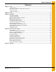
Table of Contents Contents Chapter 1 Safety .....................................................................................................................................................4 Safety Guidelines .................................................................................................................................. 4 Fan/Heater Installation and Operating Instructions ............................................................................... 5 Safety Precautions .............
1. Safety Safety Guidelines This manual contains information that is important for you, the owner/operator, to know and understand. This information relates to protecting personal safety and preventing equipment problems. It is the responsibility of the owner/operator to inform anyone operating or working in the area of this equipment of these safety guidelines. To help you recognize this information, we use the symbols that are defined below. Please read the manual and pay attention to these sections.
1. Safety Fan/Heater Installation and Operating Instructions Thank you for choosing a Top Dry Series 2000 Fan/Heater unit. It is designed to give excellent performance and service for many years. This manual describes the installation for all standard production Top Dry Series 2000 single fan, multi-fan and 2000 series heater control units. Different models are available for liquid propane or natural gas fuel supply, with either 1 phase 230 volt or 3 phase 208, 220, 380, 460 or 575 volt electrical power.
1. Safety Use Caution in the Operation of this Equipment This dryer is designed and manufactured with operator safety in mind. However, the very nature of a grain dryer having a gas burner, high voltage electrical equipment and high speed rotating parts, presents hazards to personnel which cannot be completely safeguarded against without interfering with the efficient operation of the dryer and reasonable access to its components.
1. Safety Safety Sign-Off Sheet As a requirement of O.S.H.A., it is necessary for the employer to train the employee in the safe operating and safety procedures for this equipment. This sign-off sheet is provided for your convenience and personal record keeping. All unqualified persons are to stay out of the work area at all times. It is strongly recommended that another qualified person who knows the shut down procedure be in the area in the event of an emergency.
2. Decals The GSI recommends contacting your local power company and having a representative survey the installation so the wiring is compatible with their system and adequate power is supplied to the unit. Safety decals should be read and understood by all people in the grain handling area. The rotating blade, fire warning decals and voltage danger decal must be displayed on the fan can.
2. Decals Rotating flighting will kill or dismember. Flowing material will trap and suffocate. Crusted material will collapse and suffocate. Keep clear of all augers. DO NOT ENTER this bin! HIGH VOLTAGE. Will cause serious injury or death. Lockout power before servicing. If you must enter the bin: 1. Shut off and lock out all power. 2. Use a safety harness and safety line. 3. Station another person outside the bin. 4. Avoid the center of the bin. 5. Wear proper breathing equipment or respirator.
3. Installation Fan/Heater Mounting 1. Inspect the fan platform for proper installation per instructions in the Top Dry erection manual. 2. Raise the Top Dry Fan/Heater units to the platform. Use the Table below to determine the height of the platform from the base of the Top Dry unit. 3. Mount the Top Dry Fan/Heater units to the bin entrance sheets. Fan legs should set on the platform.
3. Installation Figure 3B Control Box Mounted on Bin Figure 3C Illustration of the bolt pattern for the manual and econo control center.
3. Installation Grain Temperature Sensor Installation 1. Remove the two (2) wires attached to the grain temperature sensor connected to terminal #22 and terminal #23 in the fan control box. 2. Mount the grain temperature sensor bracket on an outside leveling band post. (See Figure 3E on Page 13.) 3. Mount the brackets with bin bolts so that the sensor is 17-1/2" above the floor sheet rib. 4. Wire tie the cord so that it feeds up the leveling band post and across the top leveling band. 5.
3. Installation Grain Temperature Sensor Installation (Continued) Figure 3E Illustration of grain temperature sensor mounted on outside leveling band post.
3. Installation Master Heater Control Box Figure 3F Illustration of the connection between the master heater control box and the drying chamber.
3. Installation Multi-Grain Temperature Sensor 1. Remove the two (2) wires attached to the grain temperature sensor connected to terminal #22 and terminal #23 in the fan control box. 2. Mount the four (4) grain temperature sensor brackets evenly around the drying chamber on outside leveling band posts. (See Figure 3E on Page 13.) 3. Mount the bracket with bin bolts so the sensor is 17-1/2" above the floor sheet rib. 4.
3.
3. Installation Top Dry Plenum High-Limit Installation 1. Assemble two (2) pieces of conduit together with coupler. 2. Mount conduit clamps to conduit assembly. 3. Locate conduit assembly on the bottom of a rafter at least 2' to one side of the fan entrance. Do not install between 2 fan entrances. 4. Mark bin wall where conduit will pass through and drill a hole just large enough to allow the conduit to pass through. Seal hole with caulking when complete. 5.
3. Installation Plenum Temperature Sensor The plenum temperature sensor is the small grey PVC junction box attached by a cord to the fan/heater control box on the master fan/heater unit. 1. On the right side of the far right fan/heater, drill one 3/4" hole even with the fan/heater unit in a valley on the bin sidewall. 2. Insert the probe through the 3/4" hole. 3. Position the housing so the cord exits the housing horizontally and the tabs fall on the sidewall peaks. 4.
3. Installation Drying Chamber Overflow Rotary Switch 1. Drill a 2" diameter hole through the roof panel at the location shown in Figure 3L on Page 20. 2. Use the mounting plate as a pattern and drill four (4) 3/8" holes through the roof panel at the switch location so the plate can be bolted to the roof. 3. Attach the flex coupling to the rotary switch power pack using a roll pin. 4.
3.
3. Installation Storage Chamber High-Limit Rotary Switch 1. Drill a 2" diameter hole through the sidewall 3' below the fan/heater. 2. If the bin is 2.66" corrugation the hole should be centered on an outside hill. 3. If the bin is 4.00" corrugation the hole should be centered on an outside valley. 4. Use the mounting plate as a pattern and drill four (4) 3/8" holes through the sidewall at the switch location so the plate can be bolted to the bin. 5.
3.
3. Installation Liquid Propane (LP) Top Dry dryers have internal vaporizers and are designed to operate on liquid draw from the supply tank. Avoid using propane supply tanks that have been used for vapor draw for long periods of time. When using liquid draw systems, any moisture that may be present in tanks or lines may freeze when the system is used in cold weather. To avoid this situation, purge the system with methanol.
3. Installation Natural Gas (NG) This dryer is designed to operate on natural gas. Natural gas units have a larger orifice to accommodate lower pressures sometimes found with natural gas and do not have vaporizer coils like liquid propane units. A regulated pressure of 10 PSI minimum, 30 PSI maximum must be provided at the field connection point on the fan/heater unit, with gas available in sufficient volume to maintain the operating pressure.
4. Electrical Power Supply Power Supply An adequate power supply and proper wiring are important factors to achieve maximum performance and long life of the dryer. Electrical service must be adequate enough to prevent low voltage damage to motors and control circuits. (See electrical load information on Page 29.) Transformer and Wiring Voltage Drop It is necessary to know the distance from the unit to the available transformer and the horsepower of the fan unit.
4. Electrical Power Supply Proper Installation of Ground Rod The ground rod should not be driven into dry ground. Follow these instructions for proper installation: 1. Dig a hole large enough to hold 1 to 2 gallons of water. 2. Fill hole with water. 3. Insert rod through water and jab it into the ground. 4. Continue jabbing the rod up and down. The water will work its way down the hole, making it possible to work the rod completely into the ground.
4.
4. Electrical Power Supply Power/Motor Wiring The Figure 4C details the configuration for correct main power installation. Use the diagram in conjunction with the electrical load information and wire size information provided. The diagram details the correct main power installation for 220V 1 PH, 230V 3 PH, 460V 3 PH, 575V 3 PH and 380V 3 PH 50 Hz power supplies.
4. Electrical Power Supply Electrical Load Information The Chart below provide information for the electrician wiring the grain dryer and are a reference guide for parts. It is recommended that you contact the local power company and have a representative survey the installation to see that the wiring is compatible with their system and that adequate power is supplied to the unit. NOTE: The only thing connected to the recommended service amps should be the grain dryer.
4. Electrical Power Supply Stand Alone Fan/Heater The Series 2000 Top Dry master fan/heater can operate as a stand alone fan/heater unit. If installed as a stand alone unit, no control center is used, all timers and temperatures are set at the fan/heater unit and the unit is stopped and started at the fan/heater. To wire the Series 2000 Fan/Heater unit as a stand alone unit do the following: 1. Place one jumper between terminal #2 and terminal #3 in the master fan/heater control box. 2.
4. Electrical Power Supply Economy Control Center Interconnect The Series 2000 Top Dry economy control center allows the fan/heater unit(s) to be stopped and started at the economy control center. All timers and temperatures are set at the fan/heater unit(s). To wire the economy control center to the master fan/heater unit do the following: NOTE: DO NOT use solid wire for interconnection. 1. Run four (4) 16 gauge MTW/THHN type wires from the economy control center to the master fan/heater unit. 2.
4. Electrical Power Supply Manual Control Center Interconnect The Series 2000 Top Dry manual control center allows the fan/heater unit(s) to be stopped and started and all timers and temperatures to be set at the manual control center. To wire the manual control center to the master fan/heater unit do the following: NOTE: DO NOT use solid wire for interconnection. 1. Run five (5) 16 gauge MTW/THHN type wires from the manual control center to the master fan/heater unit. 2.
4. Electrical Power Supply Master to Slave Interconnect A slave fan/heater unit can be added to operate in unison with the master fan/heater unit. The interconnect between the master and slave fan/heater units remains the same regardless of the type or presence of a control center. To wire a slave fan/heater unit to a master fan/heater unit do the following: NOTE: DO NOT use solid wire for interconnection. 1.
4. Electrical Power Supply Slave to Slave Interconnect A second slave fan/heater unit can be added to operate in unison with the master fan/heater unit and another slave fan/heater unit. This would create a three (3) fan unit. The interconnect between the first slave fan/heater unit and the second slave fan/heater unit remains the same regardless of the type or presence of a control center.
4. Electrical Power Supply Rotary Switch and Horn Wiring A drying chamber overflow rotary switch and a storage chamber high level rotary switch can be used to let the operator know when the drying chamber or the storage chamber is full. Figure 4I details one possible way of wiring both the drying chamber and the storage chamber rotary switches so that the horn will sound when either the drying chamber or the storage chamber is full. To wire the rotary switches and the horn do the following: 1.
NOTES 36 PNEG-634 2000 Top Dry Fan/Heater
5. Warranty GSI Group, LLC Limited Warranty The GSI Group, LLC (“GSI”) warrants products which it manufactures to be free of defects in materials and workmanship under normal usage and conditions for a period of 12 months after sale to the original end-user or if a foreign sale, 14 months from arrival at port of discharge, whichever is earlier.
This equipment shall be installed in accordance with the current installation codes and applicable regulations which should be carefully followed in all cases. Authorities having jurisdiction should be consulted before installations are made. GSI Group 1004 E. Illinois St. Assumption, IL 62510-0020 Phone: 1-217-226-4421 Fax: 1-217-226-4420 www.gsiag.