2', 18', 24' and 30' GSI Commercial Tower Dryer Construction Manual PNEG-707 Date: 02-26-09 PNEG-707
PNEG-707 12', 18', 24' and 30' GSI Commercial Tower Dryer
Table of Contents Contents Chapter 1 Introduction ....................................................................................................................................... 6 Chapter 2 Safety .................................................................................................................................................. 7 Safety Guidelines ...............................................................................................................................
Table of Contents Chapter 5 Plenum Roof ..................................................................................................................................... 46 Plenum Roof Components (Expanded View) ................................................................................... 46 Plenum Roof (Aerial View) ............................................................................................................... 47 Plenum Roof (Cross Section) ........................................
Table of Contents Chapter 15 Fans, Divider Hopper, Reducer Walkway .................................................................................. 154 Fan Splicing and Reducer Walkway - All Models ......................................................................... 154 Fan X-Bracing - All Models ........................................................................................................... 155 Fan X-Bracing, Divider Hopper, and Reducer Walkway Model 2500 .................................
1. Introduction READ THIS MANUAL carefully to learn how to properly use and install equipment. Failure to do so could result in personal injury or equipment damage. INSPECT the shipment immediately upon arrival. The customer is responsible for ensuring that all quantities are correct. The customer should report and note any damage or shortage on the bill of lading to justify their claim to the transport company.
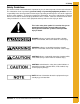
2. Safety Safety Guidelines This manual contains information that is important for you, the owner/operator, to know and understand. This information relates to protecting personal safety and preventing equipment problems. It is the responsibility of the owner/operator to inform anyone operating or working in the area of this equipment of these safety guidelines. To help you recognize this information, we use the symbols that are defined below. Please read the manual and pay attention to these sections.
2. Safety General Safety Statement Our foremost concern is your safety and the safety of others associated with grain handling equipment. This manual is to help you understand safe operating procedures and some problems which may be encountered by the operator and other personnel. As owner and/or operator, you are responsible to know what requirements, hazards and precautions exist and inform all personnel associated with the equipment or in the area. Safety precautions may be required from the personnel.
3. Safety Decals Some of the required safety decals are placed on the dryer before shipping. The remainder are placed on the dryer during electrical installations. The purpose of the safety decals is to immediately alert all personnel to the hazards of an operating dryer. The safety decal does not replace the need for all personnel to know and understand safe dryer operations and requirements. Read the “Dryer Operations and Service Manual”.
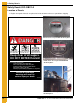
3. Safety Decals Safety Decal # DC-GBC-1A Location of Decals 1. English and spanish decals are placed on inside of tower roof access port before shipping. Tower roof access port with decals in place. Rotating flighting will kill or dismember. Flowing material will trap and suffocate. Crusted material will collapse and suffocate. Keep clear of all augers. DO NOT ENTER this bin! If you must enter the bin: 1. Shut off and lock out all power. 2. Use a safety harness and safety line. 3.
3. Safety Decals Safety Decal # DC-889 Location of Decal 1. On outside of main power box, on right door. 2. On outside of main power box, on left door. 3. Inside main power box door, on same side as main electrical disconnect.
3. Safety Decals Safety Decals # DC-985, DC-990 and DC-991 Location of Decal Inside main power box door, on same side as main electrical disconnect.
3. Safety Decals Safety Decals # DC-987, DC-988 and DC-989 Location of Decal Inside main power box door, on same side as main electrical disconnect.
3. Safety Decals Safety Decal # DC-1060 Location of Decal 1. On outside of hopper service door. 2. On outside of hopper service door. 1 2 Safety Decal # DC-1061 Location of Decal 1. On outside of heat section door. WARNING! 1 Flame and pressure beyond door. May cause serious injury. Do not enter when dryer is running.
3. Safety Decals Safety Decals # DC-1063 and DC-1064 Location of Decal On outside of cool section door. WARNING! High speed belt drive operating overhead. Can cause serious injury. Keep head and hands clear. Do not enter when dryer is running. DC-1064 CAUTION! Airborne particles during operation. May impair vision and breathing. Do not enter when dryer is running.
3. Safety Decals Safety Decals # DC-1223 and DC-1317 Location of Decal 1. On outside of main power box door, to left of main electrical disconnect. 2. On outside of main power box door, above emergency stop disconnect. Main Electrical Disconnect Disconnects load side power.
3. Safety Decals Information Decals Name Plate for Main Power Box Location of Decal 1. Inside main power box door, on same side as main electrical disconnect.
3. Safety Decals GSI Decal The standard location for the GSI decal is on the side of the dryer that can be seen from the operating facility and/or from access road. GSI decal will be centered on top two (2) solid wall sheets, just below roof section. Remove nuts and bolts from the seam of those two (2) solid wall sheets. Remove backing from GSI decal. Center and apply GSI decal to top two (2) solid wall sheets. Smooth out air bubbles. Remove masking from front of GSI decal.
4. Orientation Wall Sheets and Vertical Channels Dryer Structure Overview The tower dryer is divided into three (3) sections: Heat section, cool section, and hopper. The following major features are installed in these sections. Heat section is about 70% of dryer. Grain is loaded into top of tower dryer (between tower roof and plenum roof), and dried in heat section. 1. Grain turners, which turn grain so it drys uniformly, are located about midpoint. 2.
4.
4. Orientation Wall Sheets and Vertical Channels Dimensions for all Models There are four (4) models of 18' diameter dryers, #2500, #3000, #3500, and #4000. These dryers are named for their BPH (bushels per hour capacity based on 20% to 15% moisture content).
4.
4.
4.
4.
4. Orientation Wall Sheets and Vertical Channels Pre-assembly This construction manual provides directions for installation of parts starting at the top section of the dryer and building down. Some installations can be done simultaneously, and some can be pre-assembled. The following installations can be pre-assembled on the ground before installing them to the dryer. 1. Interior and exterior walkway sections. (Catwalk and platform.) 2. May need to pre-assemble reducer housing. 3.
4. Orientation Wall Sheets and Vertical Channels Layout and Clearance (Continued) 7. Locate the electrical control system (consists of power box and control box) for the convenience of the dryer operator, where visibility and access are best. Can locate control box directly below a motor window to allow installation of wiring conduit in a direct run. (Advisable or Recommended.) 8.
4.
4.
4.
4.
4.
4.
4.
4.
4. Orientation Wall Sheets and Vertical Channels Wall Sheets Overlap Throughout Dryer Wall sheets are installed in overlapping rings around dryer, starting at dryer top and working down. Each ring of sheets vertically overlaps the ring of sheets above it so that grain does not lodge between. Each sheet installed horizontally overlaps the previous sheet in the ring. In Figure 4P, sheet (B) laps sheet (1A), (C) laps (B), and so on around the dryer.
4. Orientation Wall Sheets and Vertical Channels Wall Sheet Comparison E C F1 B G H A Figure 4R Outside Wall Sheets - Stainless Steel Figure 4Q Inside Wall Sheets - Galvanized E. Outside wall sheet, perforated, 20" high 0.078" (big hole). A. Inside top wall sheet (perforated), 30" high. Use for inside plenum roof wall. B. Inside heat/cool wall sheet (perforated), 40" high. Use same part to form inside heat wall and inside cool wall. F1. Outside wall sheet, solid, 20" high.
4. Orientation Wall Sheets and Vertical Channels Wall Sheet Guidelines Inside wall sheets (and hardware) are galvanized, and form plenum chamber wall of dryer. Outside wall sheets (and hardware) are stainless steel, and form tower wall of dryer. These two (2) walls of the dryer are separated by columns of vertical channels. This structure forms grain columns through which grain flows. Each perforated wall sheet has a rough side and a smooth side.
4.
4.
4. Orientation Wall Sheets and Vertical Channels Example - Installing Wall Sheets to Roof Figure 4V Hanging inside wall sheets. Figure 4X Close Up - Installing rolled plenum channels. Figure 4W Installing rolled plenum channels. Figure 4Y Tightening inside wall sheets. Figure 4Z Installing lift brackets to outside wall sheets of tower roof. (With 3/8" x 1" galvanized bolts and nuts.
4. Orientation Wall Sheets and Vertical Channels Lifting Dryer Guidelines Tower dryer is built from roof down, rather than from the ground up. Dryer is lifted to install each set of vertical channels and other components. From below dryer roof to hopper, each lift will have two (2) rows of inside wall sheets and four (4) rows of outside wall sheets installed to each set of vertical channels. Customarily, jacks are used to lift dryer during construction.
4. Orientation Wall Sheets and Vertical Channels Vertical Channel Comparison Y A B C D E Z GT4-0248V GT4-0249V X A. Vertical channel - 80", 10 gauge B. Vertical channel - 80", 8 gauge X. Vertical channel - 80", 8 gauge (bolt holes in side are evenly spaced.) C. Vertical channel, 40", 8 gauge Use as required to fill in vertical channel column. Y. Vertical channel - 80", 10 gauge (three (3) bolt holes in center of side are spaced closely together.) D. R.H.
4.
4.
5. Plenum Roof Plenum Roof Components (Expanded View) Figure 5A Parts in Order of Installation 46 Qty A Jig Clips (not shown) 12 B Vertical Channels 12 C Inside Top Wall Sheets 12 D Rolled Plenum Channels (not shown) 6 E Plenum Eave Channels 6 F Plenum Eave Channel Splices 6 G Plenum Roof Center Collar 1 H Plenum Roof Rafters (R.H.) 9 I Plenum Roof Rafters (L.H.
5. Plenum Roof Plenum Roof (Aerial View) Figure 5B Parts E Plenum Eave Channels G Plenum Roof Center Collar H Plenum Roof Rafters (R.H.) I Plenum Roof Rafters (L.H.) J Rafter Crossmember - Short Top K Rafter Crossmember - Short Bottom L Rafter Crossmember - Long Top M Rafter Crossmember - Long Bottom N Plenum Roof Flashing O Plenum Roof Sheets NOTE: Plenum eave channel splice is not shown.
5. Plenum Roof Plenum Roof (Cross Section) Figure 5C Parts 48 B Vertical Channels C Inside Top Wall Sheets D Rolled Plenum Channels E Plenum Eave Channels F Plenum Eave Channel Splices (not shown) G Plenum Roof Center Collar H Plenum Roof Rafters (R.H.) I Plenum Roof Rafters (L.H.
5.
5.
5. Plenum Roof Figure 5H Figure 5I Key = Jig clips install to foundation at intervals of 4' 1-1/4" around circle A. = Vertical channels are bolted to jig clips. NOTE: Note orientation of vertical channels. Each vertical channel mirrors the previous one.
5. Plenum Roof Important Safety Precautions: Dryer has sharp edges. These sharp edges may cause serious injury. Use appropriate personal protective equipment. Use proper lifting techniques. See Orientation Section on Page 19 for dryer dimensions, components, wall sheet guidelines, etc. See Appendix A on Page 435 for tools and equipment, Appendix B on Page 437 for hardware, etc. Steps to Construct Plenum Roof Jig Clips Install jig clips as follows.
5. Plenum Roof Vertical Channels Bolt 10 gauge vertical channel to each jig clip. Use 3/8" x 1" bolts. Alternate the direction of each vertical channel so that each mirrors the previous one. In other words, bolt vertical channels so they are facing [ ], then opposing ] [, then facing, and so on around perimeter of dryer. See vertical channel comparison in Orientation Section on Page 19. Figure 5L Vertical channels are facing [ ].
5. Plenum Roof Figure 5O Figure 5N Rolled Plenum Channels Install 1 ring of rolled plenum channels to reinforce the ring of inside top wall sheets as follows. 1. Bolt one (1) plenum channel splice to each rolled plenum channel with 5/16" x 1" whiz bolt and nut before installing to dryer. Figure 5P Plenum Channel Splice Figure 5Q Plenum Channel Splices - as shipped. Throughout Dryer Install rings of rolled plenum channels to wall sheets so closely that fingers will not fit between them. 2.
5. Plenum Roof 3. Test fit. Install rings of rolled plenum channels to wall sheets so closely that fingers will not fit between them. Figure 5R Rolled Plenum Channel 4. After entire ring of rolled plenum channels is installed to this section of the dryer, tighten bolts. If gap/space is observed between sheet and channel (post tightening) drill holes and use 5/16" x 3/4" galvanized bolts and nuts to close the space. (This will prevent flexing movement resulting in sheet tears.
5. Plenum Roof Plenum Eave Channels and Plenum Eave Channel Splices Snug bolt plenum eave channels to vertical channels with two (2) 3/8" x 2" grade 8 hex head bolts and nuts per vertical channel. Insert bolts in two (2) bottom bolt holes of three (3) bolt holes that are spaced closely together. (Plenum roof flashing will be installed in top bolt hole.) Splice plenum eave channels together with plenum eave channel splices. Use 3/8" x 2" grade 8 hex head bolts and nuts.
5. Plenum Roof Eave channel splice Three (3) closely spaced bolt holes on vertical channel. Figure 5X Installing eave channels to vertical channels. Plenum Roof Rafters (Right Hand and Left Hand) and Plenum Roof Center Collar Install (18 R.H. and L.H.) plenum roof rafters around roof of dryer as follows. (See Figure 5A on Page 46, Figure 5B on Page 47 and Figure 5C on Page 48.) (See Figure 5AB-Figure 5AI.) 1.
5. Plenum Roof Snug bolt tops of plenum roof rafters to plenum roof center collar. Use 3/8" x 1" hex head galvanized bolts and nuts. Snug bolt bottoms of plenum roof rafters in pairs of bolt holes along top of eave channel. Use 3/8" x 1-1/4" grade 8 hex head bolts and nuts. (3/8" Galvanized washers as needed.) 2. Snug bolt two (2) more plenum roof rafters to plenum roof center collar. Orient to bolt holes in plenum roof center collar as shown in Figure 5Z. L.H. L.H. R.H. R.H. Figure 5Z 3.
5. Plenum Roof Figure 5AB Plenum Roof Center Collar Figure 5AD Top of plenum roof rafters installs to center collar. L.H. R.H. Figure 5AC A pair of plenum roof rafter are right hand and left hand. R.H. and L.H. mirror each other. Figure 5AE Bottom of plenum roof rafters installs to eave channel.
5. Plenum Roof Figure 5AF From opposite sides of dryer, bring a (R.H. and L.H.) pair of plenum roof rafters together in center of dryer. Figure 5AI Close Up - Bolt top of plenum roof rafters to plenum roof center collar. Figure 5AG Bring first pair of plenum roof rafters together to plenum roof center collar in center of dryer Figure 5AJ Close Up - Bolt bottom of plenum roof rafters to top of plenum roof eave channel (in pairs of bolt holes).
5. Plenum Roof Rafter Crossmembers Install rafter crossmembers between plenum roof rafters as illustrated in Figure 5AL-Figure 5AN. Snug bolt with 5/16" x 1" hex head bolts and nuts until all are installed, then tighten. D B C A B A C D Up A. Rafter crossmember - long bottom B. Rafter crossmember - short bottom C. Rafter crossmember - long top D. Rafter crossmember - short top Figure 5AK Install rafter crossmembers as marked.
5. Plenum Roof Plenum Roof Flashing Install plenum roof flashing (with tabs down) over inside top plenum wall sheets. Overlap plenum roof flashing. Snug bolt with 5/16" x 1" whiz bolts and nuts. Do not tighten bolts in tabs on flashing until after plenum roof sheets are installed. Figure 5AN Installing plenum roof flashing with tabs over inside top wall sheets. X X X X X Figure 5AO Tabs on plenum roof flashing are marked by “X”.
5. Plenum Roof Plenum Roof Sheets Bolt plenum roof sheets over plenum roof rafters and over plenum roof flashing as follows. Use 5/16" x 1" whiz lock galvanized bolts and nuts. Insert bolts toward inside of dryer. NOTE: Leave two (2) outside bolt holes on peak of plenum roof sheets open. Peak cap will be installed there. (See Figure 5AQ.) Overlap plenum roof sheets so that each sheet overlaps previous sheet with common bolts.
5. Plenum Roof Figure 5AR Aligning Plenum Roof Sheets Figure 5AS Plenum roof is ready for peak cap assembly installation.
5. Plenum Roof Peak Cap and Plenum Roof Center Collar 1. Bolt plenum cone fill hopper over plenum center cone with nine (9) plenum cone offset brackets. Use 5/16" x 1" whiz lock galvanized bolts and nuts. 2. Center and level peak cap over plenum roof center collar. 3. Bolt peak cap to top of plenum roof sheets. Use 5/16" x 1" whiz lock galvanized bolts and nuts in two (2) bolt holes on outside of plenum roof sheets. A B A. Plenum cone with fill hopper B.
5. Plenum Roof Tighten remaining bolts on plenum roof Figure 5AW Tightening inside top wall sheets. (Inspect all when completed. Access is restricted after this point.) Figure 5AX Hand tightening plenum roof rafters, wall sheets, eave channels, cross members, etc. Figure 5AY Hand tightening rafter crossmembers. Figure 5AZ Interior View after lifting dryer Completed plenum roof.
6.
6.
6.
6. Tower Roof Important Safety Precautions: Dryer has sharp edges. These sharp edges may cause serious injury. Use appropriate personal protective equipment. Use proper lifting techniques. See Orientation Section on Page 19 for dryer dimensions, components, wall sheet guidelines, etc. See Appendix A on Page 435 for tools and equipment, Appendix B on Page 437 for hardware, etc. Steps to Construct Tower Roof Roof Band Use 5/16" x 3/4" stainless steel whiz lock bolts and 5/16" nuts.
6. Tower Roof Bulb Seal Press continuous strip of bulb seal over top of entire length of roof band. Figure 6F Bulb seal as shipped. Figure 6G Pressing bulb seal over top of roof band.
6. Tower Roof Eave Clip Use 5/16" x 3/4" stainless steel whiz lock bolts and 5/16" nuts. (Galvanized could be substituted here.) Snug bolt tabs of eave clips (over roof rubber seal) to outside of roof band. Use pairs of bolt holes at top of roof band. NOTE: Do not tighten bolts until after expansion ring is loosely installed to tower roof. Tabs Figure 6H Eave Clip Intermediate Eave Clip See Figure 6A on Page 67, Figure 6B on Page 68 and Figure 6C on Page 69.
6. Tower Roof Tower Roof Hardware A B C A. Bin bolt, 5/16" x 3/4", grade 5 with neoprene washer B. Hex head nut, 5/16", grade 2 C. Bin bolt, 5/16" x 1-1/4", grade 5 with neoprene washer Figure 6L A Figure 6M Close Up - Neoprene Washers B C A. Stainless steel, whiz lock Bolts = Dull gray Nuts = Shiny gray (with flange) B. Galvanized, whiz lock Bolts = Shiny gray Nuts = Yellow (with flange) C.
6. Tower Roof Tower Roof Center Collar 1. Bolt three (3) tower roof center collar sections together. Use 5/16" x 3/4" bin bolts, grade 5 bolts, 5/16" hex head nuts, and neoprene washers. NOTE: Insert bolts toward inside of center collar, with neoprene washers against outside of center collar to provide seal. 2. Position tower roof center collar above peak cap, in center of dryer. Figure 6O Tower Roof Center Collar Section (1 of 3) A B A.Tower roof sheet with cut out for tower roof access port. B.
6. Tower Roof Tower Roof Sheets, Tower Roof Rungs and Expansion Ring Clips NOTE: Install roof rungs and expansion ring clips to tower roof sheets during tower roof sheet installation. Vertical Tower Roof Seams Use 5/16" x 1-1/4" bin bolts, grade 5 bolts, 5/16" hex head nuts, and neoprene washers. Leave out second to top bolt in tower roof vertical seams for center collar flashing installation.
6. Tower Roof From opposing sides of dryer, bring first pair of tower roof sheets together to tower roof center collar in center of dryer. Position tower roof sheet with cut out for roof access port directly above where outside ladder will be installed. Snug bolt top bolt hole of tower roof sheets to outside bottom of tower roof center collar. Snug bolt bottom bolt hole of tower roof sheets to eave clips, and intermediate eave clips. Leave other bolt holes on ribs (vertical seams) open.
6. Tower Roof Install roof rungs and expansion ring clips to tower roof sheets during tower roof sheet installation. Count bolt holes (BH) from bottom of rib of tower roof sheet. • Set of four (4) roof rungs - install across tower roof sheet with cut out for access port in BH1, BH3, BH4 and BH5. • Remaining roof rungs - install across every other tower roof sheet in BH5. • Install expansion ring clips in every BH3.
6. Tower Roof Expansion Ring After expansion ring clips are installed to tower roof sheets, install expansion ring sections as follows. Use expansion ring hardware. (See Figure 6AA on Page 79.) Double nut (spin two (2) nuts closely together) each expansion bolt. NOTE: Expansion bolts should be fully contracted during installation. In other words, leave double nuts spun closely together until after expansion ring is complete. 1. Insert first expansion ring section into expansion ring clips.
6. Tower Roof Figure 6AA Installing expansion ring to expansion ring clips. Figure 6AB Close Up - Installing expansion ring and clips. Figure 6AC Double nut on fully contracted expansion bolt.
6. Tower Roof 4. Install three (3) center collar flashing sections and caulk as follows. a. Wipe oil from outside of tower roof center collar where center collar flashing section will join it. Press on strip caulking (24' rolls). b. Align vertical edge of first center collar flashing section along a seam of center collar. Tabs of center collar flashing will fit over ridges in tower roof sheets. Bolt using the following hardware.
6. Tower Roof Fill Tube Weldment Insert fill tube weldment into center collar. Figure 6AG Fill Tube Weldment Access Port Cover Install access port cover to the tower roof sheet that has a cut out for the access port as follows. (See Figure 6C on Page 69.) 1. Locate where moisture diverter will join access port tower roof sheet. Wipe area clean of oil and press on strip caulking (24' rolls) to cover bolt holes. 2. With common bolts, bolt moisture diverter, then hinge base to access port tower roof sheet.
6. Tower Roof Figure 6AH Access door cover with “DANGER - Avoid Suffocation” decals. G F A B C D E A. Moisture diverter B. Hinge Leaf C. Four (4) 10-24 x 5/8" bolts and lock nuts, handle gasket D. Hinge base E. Latch F. Handle with shaft G.
6. Tower Roof Figure 6AJ Pressing pre-cut bulb seal on rim of access port cut out on tower roof sheet. Figure 6AL Inside View - Access Port Cover Installed Figure 6AK Close Up - Access port cover installed. Figure 6AM Outside View - Access port cover installed.
6. Tower Roof Outside Wall Sheets Install two (2) rows of solid outside wall sheets (20" high) to vertical channels. NOTE: Use common bolts to install brackets for outside ladder with safety cage. (See Outside Ladder on Page 86.) Install perforated sheets as required. See Orientation Section on Page 19 for illustrations and wall sheet installation guidelines.
6. Tower Roof Bottom Section Attachment Attach using the same process as shown on Page 84. Attach using the same process as shown on Page 84. On the 2 step channel, there is only one way for the channel to attach to the previous section on Page 84.
7.
7. Outside Ladder Important Safety Precautions: Dryer has sharp edges. These sharp edges may cause serious injury. Use appropriate personal protective equipment. Use proper lifting techniques. See Orientation Section on Page 19 for dryer dimensions, components, wall sheet guidelines, etc. See Appendix A on Page 435 for tools and equipment, Appendix B on Page 437 for hardware, etc.
7. Outside Ladder 1 Outside Ladder 1. 44" Formed ladder section (also used on inside ladder) 2. Outside ladder stiffener 3. Inside ladder standoff (only used on inside ladder) 4. Ladder stiffener splice 5. Outside ladder bracket 2 3 4 5 Figure 7D A A D B B C Figure 7E Top Safety Cage C Figure 7G Bell safety cage has larger bell-shaped hoops. Safety Cage A. 44" Vertical supports B. Safety cage brackets A C. Safety cage hoop halves D.
7. Outside Ladder Top Safety Cage Pre-assemble top safety cage as follows. (See Figure 7H and Figure 7I.) 1. Snug bolt one (1) 44" formed ladder section to two (2) outside ladder stiffeners. Snug bolt four (4) safety cage brackets to outside ladder stiffeners. 2. Bolt pairs of safety cage hoop halves together. Snug bolt safety cage hoops to safety cage brackets. 3. Snug bolt seven (7) 44" vertical supports to safety cage hoop halves. 4. Snug bolt top safety cage assembly to outside ladder brackets.
7. Outside Ladder Install all 44" formed ladder sections so rungs with rough, textured side for gripping are on top, so climbers do not slip. When Assembling Ladder and Safety Cage Use 5/16" x 3/4" galvanized whiz lock bolts and nuts. When Installing Ladder and Safety Cage to Dryer Use 5/16" x 3/4" stainless steel whiz lock bolts and nuts. LADDER BOLTS - insert bolts toward outside of ladder, so climbers do not snag on bolt shafts.
7. Outside Ladder 5. Secure top safety cage to tower roof ribs as follows. • With common bolt, snug bolt first end tube to outside ladder stiffener. • Fit center tube into first end tube. • Fit second end tube into center tube. • Snug bolt second end tube to rib of tower roof above tower roof access port with existing 5/16" x 1-1/4", grade 5 bolts, hex head nuts, and neoprene washers. 6. Square top safety cage assembly.
7. Outside Ladder Safety Cage Extensions Install safety cage extensions from top safety cage to bell safety cage just above foundation as follows. Quantity depends upon dryer model. 1. Splice outside ladder stiffeners with ladder stiffener splices. Snug bolt outside ladder stiffeners behind 44" formed ladder sections. Install safety cage brackets and safety cage hoops like top safety cage. 2. Before lifting each section, tighten bolts in outside ladder with safety cage for that section.
7. Outside Ladder While Installing each Catwalk, Install Outside Ladder with Safety Cage 1. Above catwalk: Halt safety cage 7' 8' above catwalk. Continue outside ladder through catwalk. 2. Below catwalk: Measure, cut, and install safety cage 44 vertical channel supports to meet bottom of catwalk. Continue installing outside ladder with safety cage. While Installing each Platform, Secure Outside Ladder with Safety Cage to it. Bend and cut safety hoops to meet vertical uprights on catwalk or platform.
7. Outside Ladder Figure 7R Close up - Installing upper and lower safety hoops to platform vertical supports. Figure 7S View from platform - Safety hoops installed to platform vertical supports. Figure 7T Trim and bolt safety hoops to platform vertical support as necessary.
7. Outside Ladder Figure 7U Close Up - Installing bell safety cage. Bell Safety Cage About 10' above foundation, install bell safety cage as the last section of the outside ladder with safety cage. Install like safety cage extensions. (NOTE: Bottom of bell must be 7' to 8' above platform or ground directly below bell.) Figure 7V Bell safety cage installed.
7. Outside Ladder Outside Ladder from Bell Safety Cage to foundation 1. Continue installing outside ladder (no safety cage) from bell safety cage until outside ladder meets foundation. 2. Ladder Support Channels NOTE: Install ladder support channels after X-rods are installed. Use 5/16" x 1" galvanized whiz lock bolts and nuts. Measure and drill dryer Legs on both sides of outside ladder for three (3) ladder support channels. Space equally. Bolt three (3) ladder support channels to span dryer legs.
8.
8.
8. Sensors Important Safety Precautions: Dryer has sharp edges. These sharp edges may cause serious injury. Use appropriate personal protective equipment. Use proper lifting techniques. See Orientation Section on Page 19 for dryer dimensions, components, wall sheet guidelines, etc. See Appendix A on Page 435 for tools and equipment, Appendix B on Page 437 for hardware, etc.
8. Sensors Hardware Figure 8C 1/2" IMC Rigid, Threaded Conduit Figure 8E 1/2" Conduit Hanger Figure 8D 1/2" Conduit Coupling Figure 8F Insulated Clip Bindicator Parts A D A. Bindicator base B. 1-1/4" x 3/8" Pipe coupling, with two (2) roll pins C. Four (4) vane paddle, with one (1) roll pin D. Mounting bracket E. Gasket B C E Figure 8G Bindicator as shipped.
8. Sensors B A. Lower bindicator, RA4 (installed on all dryers) (N/S) B. Upper bindicator, RA6 (install only on conveyor or slide gate fill dryer) Figure 8H Bindicators (wired for demonstration) A B A. 12" x 1-1/4" Pipe guard B.
8. Sensors Bindicator(s) Assemble bindicator(s) according to instruction sheet packed with them. NOTE: See Figure 8B on Page 98 for placement of bindicator(s). 1. Lower Bindicator, RA4 Measure inner (not outer) diameter of gasket. This is the diameter of hole needed to mount lower bindicator on wall sheet. Locate wall sheet directly below access port. Center hole vertically on that wall sheet. Cut a hole in wall sheet that measures the same as gasket inner diameter.
8. Sensors High-Limits (Overheats) Install upper, middle and lower High-Limits on outside of dryer. NOTE: See Figure 8A on Page 97 for placement. For sensors to work properly, it is important to install High-Limits on perforated sheets. Not on horizontal seams. Position junction boxes with drainage holes down and behind outside ladder screw in conduit. Secure conduit close to junction box with 1/2" conduit hangers on existing bolts on seam. Wrap copper tubing entirely around dryer.
8. Sensors 1. Install upper High-Limits. Figure 8O Upper High-Limit installed with junction box under outside ladder (arrow). Figure 8P Close Up - Upper High-Limit installed with junction box positioned under outside ladder.
8. Sensors 2. Install middle High-Limits. Figure 8Q Middle High-Limit installed. Figure 8R Do not cut ends of copper capillary tubing. Overlap them.
8. Sensors 3. Install lower High-Limits. Figure 8S Installing lower High-Limit. NOTE: Outside ladder will install over junction box. Figure 8T Installing copper capillary tubing with insulated clips.
8. Sensors Grain Temperature Sensors (RTDs) Install RTDs on outside of dryer, within safe reach of ladder. There is one (1) RTD on a 10' length of 1/2" conduit. Position RTDs according to Figure 8A on Page 97. Drill hole in dryer wall for sensing bolt on each RTD. Add one (1) 3/8" washer to bolt/washer already on each RTD. Insert sensing bolt in hole. Secure conduit near RTD with 1/2" conduit hanger. Use existing bolts on seam. NOTE: Do not place nut on inside of outside screen.
8. Sensors Figure 8W Installing L.H.
9. Lift Dryer Important Safety Precautions: Dryer has sharp edges. These sharp edges may cause serious injury. Use appropriate personal protective equipment. Use proper lifting techniques. See Orientation Section on Page 19 for dryer dimensions, components, wall sheet guidelines, etc. See Appendix A on Page 435 for tools and equipment, Appendix B on Page 437 for hardware, etc. Steps to Lift Dryer Vertical Channel Splice Universal Shim Plate Splice vertical channels together with vertical channel splices.
9. Lift Dryer Example: Lifting Roof Section Before lifting roof of dryer, do safety check for wind or electrical hazards, clearance, etc. (See Orientation Section on Page 19.) Tighten all bolts on dryer (except lower ladder parts). Apply GSI decal. 1. Pre-install vertical channel splice plates to vertical channels to be installed after lift. Move vertical channels near to dryer. 2.
9. Lift Dryer 6. Lower dryer. Check to be sure bottom of vertical channel is on outside of jig clip. Figure 9F Positioning jack next to dryer. Figure 9G Checking jack is 11-1/2" to 12" from dryer. 7. At top, loosely bolt vertical channel splices to vertical channel already on dryer. At bottom, loose bolt vertical channels to jig clip to align dryer. 8. As each lift of dryer is constructed, install wall sheets, ladders, catwalks, platforms, and other dryer features as required.
9. Lift Dryer Figure 9M Bolting vertical channels. Figure 9J Raising Dryer (Crane shown here). Figure 9K Sliding vertical channel up to vertical channel on dryer. Figure 9N Close Up - Bolting vertical channels. Figure 9L Aligning vertical channels.
9. Lift Dryer Figure 9O Lowering vertical channel on outside of jig clip. Figure 9P Bolting vertical channel to jig clip. Figure 9Q Removing lift bracket.
10. Catwalks and Platforms Outside Catwalk NOTE: Ladder runs through catwalk.
10. Catwalks and Platforms Inside Catwalk Figure 10B Part # Description Qty GT1-0003 Catwalk Floor Support 16 GT1-0005 Catwalk Vertical Support 16 GT1-0006 Catwalk Diagonal Support 16 GT1-0007 Catwalk Splice Plate 16 GT1-0162 Catwalk Support Clip 32 GT1-0310 Large Floor Plank 16 GT1-0311 Medium Floor Plank 16 GT1-0312 Small Floor Plank 16 GT1-0313 Outer Toeboard 16 GT1-0314 Inner Toeboard 16 GT1-0315 Inner Catwalk Handrail 32 Quantity is for one (1) inside catwalk.
10. Catwalks and Platforms Platform Figure 10C NOTE: Safety cage tubing not shown for clarity.
10.
10.
10.
10.
10.
10.
10.
10. Catwalks and Platforms Important Safety Precautions: Dryer has sharp edges. These sharp edges may cause serious injury. Use appropriate personal protective equipment. Use proper lifting techniques. See Orientation Section on Page 19 for dryer dimensions, components, wall sheet guidelines, etc. See Appendix A on Page 435 for tools and equipment, Appendix B on Page 437 for hardware, etc. Steps - Catwalks and Platforms 1. Outside catwalk(s) (one (1) or two (2)) 2. Inside catwalk 3.
10. Catwalks and Platforms Outside Catwalk (*= Door parts) A. *Outside catwalk hinged door section B. *Outside catwalk door section C. Outside catwalk section A B D. Outside catwalk handrail (use for upper and lower handrail) E. *Outside catwalk outside door toeboard F. *Outside catwalk inside door toeboard Figure 10M G. Outside catwalk outside toeboard H. Outside catwalk inside toeboard I. Outside catwalk diagonal support J. Outside catwalk vertical support K. Outside catwalk floor support L.
10. Catwalks and Platforms Outside Catwalk (Continued) G H J C L J G M K C L K I M I M Figure 10R Parts are listed on Page 125. Figure 10Q Parts are listed on Page 125. Use 5/16" x 3/4" whiz lock bolts and nuts to install catwalk flooring. Use 3/8" x 1" whiz lock bolts and nuts to install handrails and supports. Figure 10S Catwalk support clip is installed with angle up on R.H. side.
10. Catwalks and Platforms Outside Catwalk (Continued) 1. Snug bolt outside catwalk diagonal support to outside catwalk support clips around perimeter of dryer. Two (2) catwalk support clips were installed on each vertical channel as wall sheets were installed. 2. Pre-assemble outside catwalk door (see Figure 10T) as follows. (Double nut at X for movement of parts.) Bolt A at “X1” to outside catwalk outside door toeboard. Bolt A at “X2” to B.
10. Catwalks and Platforms Outside Catwalk (Continued) Figure 10U Tightening outside catwalk. Figure 10X Outside Catwalk Door - Open Figure 10V Tightening outside catwalk bottom handrail. Figure 10Y Outside Catwalk Door - Closed Figure 10W Tightening outside catwalk top handrail.
10. Catwalks and Platforms Inside Catwalk For inside catwalk door, install provided continuous hinge at “X” to one (1) inside catwalk section. (See Figure 10AB.) Use 5/16" x 3/4" whiz lock bolts and nuts to install catwalk flooring. Use 3/8" x 1" whiz lock bolts and nuts to install handrails and supports. NOTE: Install inside catwalk parts in the same order as outside catwalk parts. A B C D E F G H Figure 10AA Figure 10AC Catwalk support clip is installed with angle up on R.H. side. A.
10. Catwalks and Platforms Inside Catwalk (Continued) Figure 10AD Installing inside catwalk. Figure 10AF Bolting inside catwalk splice plate to inside catwalk section. Figure 10AG View from below - Completed inside catwalk. Figure 10AE Bolting inside catwalk vertical support to inside catwalk section.
10. Catwalks and Platforms Inside Catwalk (Continued) Hinge Figure 10AJ View from below - Inside catwalk installed. (Inside catwalk door is closed.) (Ladder is not complete.) Figure 10AH View from above - Inside catwalk door closed. Figure 10AI View from above - Inside catwalk door open. Figure 10AK View from below - Inside Catwalk installed. (Inside catwalk door is open.
10. Catwalks and Platforms Platforms See flat layouts in Orientation Section on Page 32 for placement of platforms. See Figure 10C on Page 116 for platform. Use 5/16" x 3/4" whiz lock bolts and nuts. 1. For each platform, install two (2) sections of catwalk flooring (with toeboards, diagonal supports, vertical supports, and handrails.) 2. Bolt entry toeboard and end toeboard to catwalk flooring. 3. Bolt additional catwalk vertical support (at dryer) to horizontal catwalk support. 4.
11. Inside Ladders Important Safety Precautions: Dryer has sharp edges. These sharp edges may cause serious injury. Use appropriate personal protective equipment. Use proper lifting techniques. See Orientation Section on Page 19 for dryer dimensions, components, wall sheet guidelines, etc. See Appendix A on Page 435 for tools and equipment, Appendix B on Page 437 for hardwared, etc. Four (4) Auxiliary Ladders Burner Housing Ladder 1 2 1. Inside ladder standoff. 2.
11. Inside Ladders Four (4) Auxiliary Ladders (Optional) Install four (4) auxiliary ladders to inside wall sheets as follows. Use existing 5/16" x 3/4" galvanized whiz lock bolts and nuts. Prior to installation, verify tightness. Double nut with second 5/16" whiz lock nut. 1. Bolt first two (2) inside ladder standoffs on the horizontal seam between the top inside wall sheets. Start in 4th bolt hole left or right from edge of sheet. (See Figure 11E on Page 135.) 2.
11. Inside Ladders Auxiliary Ladder (Continued) Figure 11D Installing auxiliary ladder from roof section down. Bolt first two (2) inside ladder standoffs on horizontal seam between top inside wall sheets. Figure 11F Installing first auxiliary ladder through inside catwalk. Figure 11E Close Up - Top of auxiliary ladder. Figure 11G Installing first auxiliary ladder past slide gates - Clean out (grain turners).
11. Inside Ladders Auxiliary Ladder (Continued) Figure 11H Auxiliary ladders installed. (2 of 4 shown.
11. Inside Ladders One (1) Burner Housing Ladder NOTE: Install burner housing ladder after reducer walkway is complete. Drill and use 5/16" x 3/4" galvanized whiz lock bolts and nuts. 1. Install four (4) inside ladder standoffs to first 44" formed ladder section as shown in Figure 11K and Figure 11L on Page 138, then bolt it to reducer housing. 2. Install four (4) inside ladder standoffs to second 44" formed ladder section, join it to top of first 44" formed ladder section, then bolt to burner housing.
11. Inside Ladders Burner Housing Ladder (Continued) Figure 11L First 44" formed ladder section installed to reducer housing. Figure 11M Bolting second 44" formed ladder section to burner housing on opposite side. (For tarping) Figure 11N Installed burner housing ladder.
12. Slide Gates Important Safety Precautions: Dryer has sharp edges. These sharp edges may cause serious injury. Use appropriate personal protective equipment. Use proper lifting techniques. See Orientation Section on Page 19 for dryer dimensions, components, wall sheet guidelines, etc. See Appendix A on Page 435 for tools and equipment, Appendix B on Page 437 for hardware, etc. Slide Gates (For Grain Turner Clean Out) (See Figure 12A to Figure 12D.
12. Slide Gates Slide Gates at Base of Dryer (For Emergency Grain Discharge) 1. After outside bottom wall sheets (20" solid with cut outs) are installed at base of dryer, install slide gates as in Page 139. (See Figure 12B and Figure 12C.) 2. After outside hopper panels with cut outs are installed, install slide gates as in Page 139. (See Figure 12D and Figure 12E.) Silicone Figure 12B Installing slide gate plate to frame on outside bottom wall sheet and mid way sheet.
13. Grain Turners Important Safety Precautions: Dryer has sharp edges. These sharp edges may cause serious injury. Use appropriate personal protective equipment. Use proper lifting techniques. See Orientation Section on Page 19 for dryer dimensions, components, wall sheet guidelines, etc. See Appendix A on Page 435 for tools and equipment, Appendix B on Page 437 for hardware, etc. Outside Divider A B UP A. Grain turner section Install with divider edge up.
13. Grain Turners Grain Turners Install forty eight (48) grain turner sections with twelve (12) grain turner offset brackets as follows. NOTE: Four (4) grain turner sections are installed in each grain column make one grain turner. Install after inside sheets are installed. Use 5/16" x 1" galvanized hex head bolts and nuts. 1. Bolt grain turner offset brackets inside vertical channels that face each other [ ]. Vertical channels that face away from each other ] [ require no grain turner offset brackets. 2.
13. Grain Turners Figure 13E Tightening grain turner sections. Figure 13F Installed grain turners.
14.
14.
14. Burner and Reducer Important Safety Precautions: Dryer has sharp edges. These sharp edges may cause serious injury. Use appropriate personal protective equipment. Use proper lifting techniques. See Orientation Section on Page 19 for dryer dimensions, components, wall sheet guidelines, etc. See Appendix A on Page 435 for tools and equipment, Appendix B on Page 437 hardware, etc. Burner and Reducer Example: Model 3000 Burner and Burner Housing NOTE: Burner housing is straight vertical.
14. Burner and Reducer Burner and Burner Housing (Continued) Figure 14G Install rolled plenum channels across gap to maintain shape and stability. Remove rolled plenum channels when ready to move burner into dryer. Depending on model, See Figure 14A on Page 144 or Figure 14B on Page 145, burner housing. See Orientation Section on Page 32 for flat layout for heat section door frame placement. See Windows and Doors on Page 187 for windows and doors for heat section door and reducer door installation. 1.
14. Burner and Reducer Burner and Burner Housing (Continued) c. Loosely bolt pairs of burner support tees (back to back) to burner housing. Use 1/2" x 1-1/2" bolts, nuts. Install washers on outside of burner housing. Loosely bolt burner support tees to burner support brackets. Use 1/2" x 1" bolts and nuts. d. Bolt burner support clips (already on burner manifold) to burner support brackets. Use 1/2" x 1" bolts and nuts. e. Tighten all bolts. 7.
14. Burner and Reducer Burner and Burner Housing (Continued) Figure 14L Measuring to determine correct knock-outs for bolt holes. Figure 14N View inside burner housing - Installing burner mounting bracket. Figure 14M Knocking out bolt holes for burner mounting bracket. (May be pre-drilled at factory also.) Figure 14O View outside burner housing - Installing burner mounting bracket with washers.
14. Burner and Reducer Burner and Burner Housing (Continued) Figure 14P First burner support bracket installed to burner mounting bracket. Figure 14Q Installing second burner support bracket to burner mounting brackets. Figure 14R Close Up - Installing burner support bracket to burner mounting bracket. Figure 14S Installing a pair of burner support tees (back to back) to burner housing.
14. Burner and Reducer Burner and Burner Housing (Continued) Figure 14T Burner support bracket bolted to burner support clip (arrow). Figure 14V Installing burner baffles. Figure 14U Installing burner baffle supports.
14. Burner and Reducer Reducer 1. Lift burner/burner housing. Move both halves of reducer into dryer and under burner housing. Orient reducer door cut out so it faces same vertical channel as heat section burner door. This will ensure maximum light for entering completed reducer area. On completed dryer, burner will be accessed through reducer door. Orient pre-cut opening for reducer door so it will give easy access to reducer by stepping onto top of a fan or fan splicing. 2. Bolt side seams of reducer.
14. Burner and Reducer Figure 14AA Close Up - Bolting sections of reducer ring together. Figure 14AB Aligning and bolting reducer to burner housing. Figure 14AC Close Up - Bolting reducer to burner housing.
15.
15.
15.
15.
15.
15.
15. Fans, Divider Hopper, Reducer Walkway Important Safety Precautions: Dryer has sharp edges. These sharp edges may cause serious injury. Use appropriate personal protective equipment. Use proper lifting techniques. See Orientation Section on Page 19 for dryer dimensions, components, wall sheet guidelines, etc. See Appendix A on Page 435 for tools and equipment, Appendix B on Page 437 for hardware, etc.
15. Fans, Divider Hopper, Reducer Walkway Fan Parts (Continued) A B C D E A. Fan crossbeam short main B. Fan crossbeam long main C. Intermediate fan support beam D. Fan crossbeam short intermediate E.
15. Fans, Divider Hopper, Reducer Walkway Move Fans into Dryer Lift reducer/burner to clear fans and move all three (3) fans into dryer on moving dollys as follows. NOTE: This is the beginning of cool section construction. NOTE: Inside ladder is not installed in cool section. NOTE: Leave out bolts for fan support clip in vertical channels as shown for the dryer model in Figure 15C on Page 156 to Figure 15F on Page 159 for fan X-bracing. 1. Remove tape from fan drive shaft. 2.
15. Fans, Divider Hopper, Reducer Walkway Move Fans into Dryer (Continued) Figure 15Q Checking clearance for fan under reducer/burner. Figure 15R Remove fan drive shaft key and save it. (Do not discard.) Figure 15S Lifting tackle is attached to fan lift eyelets. Figure 15T Stand fan up vertical with drive shaft down on dolly.
15. Fans, Divider Hopper, Reducer Walkway Move Fans into Dryer (Continued) Figure 15U Move fans to dryer. Figure 15V Pushing fans into dryer. Figure 15W Three (3) fans form a cluster inside dryer. Figure 15X Re-installing vertical channel after fans are inside dryer.
15. Fans, Divider Hopper, Reducer Walkway Move Fans into Dryer (Continued) Figure 15Y Measuring to exactly center fan cluster inside walls of dryer. Figure 15AA Note location of upper grease zerk for installation of grease tube in later step.
15. Fans, Divider Hopper, Reducer Walkway Splicing To close in space around fans, install fan housing splice and six (6) fan reducer panels as follows. See Figure 15A on Page 154 for fan splicing. 1. Lower reducer/burner down to top of fans. Check lower ring of reducer is centered over fan cluster. Align lower ring of reducer with two (2) outer bolt holes in top ring of each fan. Check fans are level. Check reducer is exactly centered within inner wall of dryer. 2.
15. Fans, Divider Hopper, Reducer Walkway X-Bracing X-Bracing forms an “X” between clips on fans and clips on vertical channels. For placement of clips and X-bracing, see Figure 15C on Page 156 to Figure 15F on Page 159 for the dryer model. NOTE: At this point, reducer walkway support clips can be installed to inside wall sheets with existing bolts. Reducer walkway is installed in later step. 1. Bolt two (2) fan support clips to each vertical channel. Use 3/8" x 1" bolts and 1/2" nuts. 2.
15. Fans, Divider Hopper, Reducer Walkway X-Bracing (Continued) X B A Figure 15AM L.H. View of bracing installed to fan support clip. A B A. Fan support clips B. Fan crossbeam clips X. Reducer walkway support clips can be installed at this point. Reducer walkway is installed in later step. Figure 15AN R.H. View of bracing installed to fan support clip. Figure 15AK Clips installed. Figure 15AL Top of fan - Installing fan crossbeam to fan crossbeam clip.
15. Fans, Divider Hopper, Reducer Walkway X-Bracing (Continued) Figure 15AP X-Bracing installed.
15. Fans, Divider Hopper, Reducer Walkway Fan Skirting To install fan skirting sections around top of fans, snug bolt widely spaced tabs on top of fan skirting sections to bottom ring of reducer. Snug bolt fan skirting sections together. (See Figure 15AU.) NOTE: Leave fan skirting loose until after installing reducer walkway support beams. Use 5/16" x 1" bolts and 1/2" galvanized nuts with washers. Figure 15AT Aligning fan skirting section to bottom ring of reducer. Widely spaced tabs on fan skirting.
15. Fans, Divider Hopper, Reducer Walkway Divider Hopper Divider hopper is formed by joining inner divider hopper sections and outer divider hopper sections in a “V” shape. Divider hopper encircles fan cluster. Divider hopper divides heat section from cool section. Divider hopper fits between fan skirting and inner wall of dryer. For divider hopper placement in the dryer model, see Figure 15C on Page 156 to Figure 15F on Page 159. Keep “V” of divider hopper level. 1.
15. Fans, Divider Hopper, Reducer Walkway Divider Hopper (Continued) 2. Align and snug bolt bottom tabs (widely spaced) on outer divider hopper sections to bottom tabs on inner divider hopper sections. Use 5/16" x 1-1/4" galvanized bolts and nuts. Space tabs with 3/8" nut in between. (See Figure 15BB.) Snug bolt outer divider hopper sections together. Use 5/16" x 3/4" galvanized bolts and nuts. 3. Drill inside wall sheets to meet bolt holes in top tabs of outer divider hopper. Snug bolt.
15. Fans, Divider Hopper, Reducer Walkway Divider Hopper (Continued) Figure 15BC Drilling bolt holes in inside wall sheets to bolt to outer divider hopper. Figure 15BD Close Up - bolting outer divider hopper to inside wall sheet. Figure 15BF View from above divider hopper NOTE: Wait to tighten divider hopper and fan skirting until after installing reducer walkway support beam (arrow).
15. Fans, Divider Hopper, Reducer Walkway Reducer Walkway For reducer walkway placement in the dryer model, see Figure 15C on Page 156 to Figure 15F on Page 159. Reducer walkway encircles fans. Keep reducer walkway level. 1. Bolt reducer walkway support clips to inside wall sheets with existing bolts (unless reducer walkway support clips were installed when fan X-bracing was installed.) (See Figure 15AK on Page 168.) 2. Install all reducer walkway support beams as follows.
15. Fans, Divider Hopper, Reducer Walkway Reducer Walkway (Continued) Figure 15BL Aerial view - Completed installation of burner, reducer, fans and divider hopper under reducer walkway. Figure 15BK Close Up - Inserting tab of reducer walkway slat into slot on reducer walkway support beam.
16. Fan Motors Important Safety Precautions: Dryer has sharp edges. These sharp edges may cause serious injury. Use appropriate personal protective equipment. Use proper lifting techniques. See Orientation Section on Page 19 for orientation for dryer dimensions, components, wall sheet guidelines, etc. See Appendix A on Page 435 for tools and equipment, Appendix B on Page 437 for hardware, etc. NOTE: Install fan motors before installing dryer windows.
16. Fan Motors Fan Motor Mounts (Continued) Figure 16C Moving fan motor mount under fan. Figure 16D Align fan motor mount and bolt to fan. Figure 16E Bolting motor mount to bottom ring of fan. Figure 16F Tightening bolts on fan motor mount. Figure 16G Fan motor mount installed. IMPORTANT: Take all appropriate safety action while working under blowers/fans.
16. Fan Motors Fan Motors Install fan motor to each fan motor mount as follows. Lift or lower dryer as necessary to install fan motors. 1. Attach lifting tackle to fan motor. (See Figure 16H.) Lift fan motor onto fan motor mount, with drive shaft up. 2. Bolt fan motor to fan motor mount in bolt holes appropriate to motor size. May be necessary to lift dryer to insert bolts. Use 5/8" x 2" bolts, nuts and washers from standard hardware kit. 178 Figure 16H Attach lifting tackle to fan motor.
16. Fan Motors Sheaves Install sheaves to each fan motor mount as follows. 1. Lift dryer for clearance. 2. Motor drive shaft. Install motor hub to motor drive shaft. Insert motor hub key. Set set screw. Slide motor sheave on motor drive shaft and bolt. 3. Fan drive shaft. Install fan hub to fan drive shaft. Insert fan hub key. Tighten set screw. Slide fan sheave on fan drive shaft and bolt. 4. Align top of motor sheave level with top of fan sheave. Check with level.
16. Fan Motors Sheaves (Continued) Figure 16O Tightening set screw on motor hub. Figure 16R Sliding fan hub on fan drive shaft. Figure 16P Sliding motor sheave on motor drive shaft. Figure 16S Placing fan hub key in fan hub. Figure 16Q Inserting motor sheave to motor hub. Figure 16T Tightening set screw on fan hub.
16. Fan Motors Sheaves (Continued) Figure 16U Sliding fan sheave on fan drive shaft. Figure 16W Tightening fan sheave bolts. Figure 16V Checking top of motor sheave is level with top of fan sheave. Figure 16X Tightening motor sheave bolts. NOTE: Final tightening of bolts should be with torque wrench.
16. Fan Motors Fan Belts When installing fan belts, do not catch fingers in fan belts. 1. For each fan, run fan belts from motor sheave to fan sheave. 2. To tighten fan belts, tighten adjusting nuts on two (2) rods on motor mount. Do not overtighten fan belts. Check fan belt tension. Fan belts will press down one fan belt width. (See Figure 16AC on Page 183.) Figure 16Y Fan belts Adjust motor mount in and out as necessary to achieve good belt tension. Figure 16Z Running fan belts in grooves on sheaves.
16. Fan Motors Figure 16AB Checking fan belt tension. Can press down about one fan belt width. Figure 16AC Once belts have proper tension, tightening adjusting nuts on bottom rod of motor mount. Figure 16AD Fan sheave and belts installed.
17. Grease Tubes Important Safety Precautions: Dryer has sharp edges. These sharp edges may cause serious injury. Use appropriate personal protective equipment. Use proper lifting techniques. See Orientation Section on Page 19 for dryer dimensions, components, wall sheet guidelines, etc. See Appendix A on Page 435 for tools and equipment, Appendix B on Page 437 for hardware, etc. NOTE: Upper bearing on fan requires grease tube for access. NOTE: Lower bearing on fan requires no grease tube.
17. Grease Tubes Figure 17H Screwing grease zerk into coupling on beam clamp end of grease tube. Figure 17E Accessing upper grease zerk. Figure 17F Grease zerk on fan (circled). Figure 17I Elbow and brass compression union installed to fan (circled). Figure 17G Grease zerk removed from fan.
17. Grease Tubes Figure 17J Attaching grease tube to brass compression union. Figure 17K Attaching beam clamp to bottom edge of fan/motor mount/or easily accessible for service. (While clearance from moving parts.
18. Windows and Doors Important Safety Precautions: Dryer has sharp edges. These sharp edges may cause serious injury. Use appropriate personal protective equipment. Use proper lifting techniques. Orientation Section on Page 19 for dryer dimensions, components, wall sheet guidelines, etc. See Appendix A on Page 435 for tools and equipment, Appendix B on Page 437 for hardware, etc. NOTE: See Orientation Section on Page 32 for flat layout for window and door placement in the dryer model.
18. Windows and Doors Hardware Assembling window frame Use 5/16" x 3/4" slotted truss head bolts and 5/16" whiz lock nuts. Installing window frame to dryer wall sheets. Drill for 5/16" x 1" whiz lock bolts and nuts. (Stainless steel on outside, and galvanized on inside.) Window screening Double nut window screening to windows with existing bolts on outside wall sheets. Louvered assembly 5/16" x 3/4" whiz lock bolts and nuts. Figure 18D Use metal shear to cut wall sheets and screen.
18. Windows and Doors Pre-assembly of Window Kits Pre-assemble 18" and 24" window kits in the same way. Figure 18J Assemble window frame, using 5/16" x 3/4" slotted truss head bolts and 5/16" whiz lock nuts. Figure 18G On a raised support, layout inside wall sheets that will support assembled window. Lap wall sheets as they should be lapped on dryer. Figure 18H Align bolt holes in the two (2) wall sheets.
18. Windows and Doors Pre-assembly of Window Kits (Continued) Figure 18P Close Up - Aligning wall sheets to window frame so bolt holes can be drilled. Note wall sheets are installed on top of window frame flange. Figure 18M Close Up - Mark window frame bolt holes. Figure 18N Line marked (by arrow) is inside perimeter of window frame. Cut on outside of line because wall sheets will lie inside window frames. NOTE: Can save wall sheet cut out to use as a pattern on next dryer installed.
18. Windows and Doors Installation of Window Kits (18" and 24") Install 18" and 24" window kits in the same way. Read section Screened Windows on Page 194 to Heat Section Door on Page 198 for additional installation information. Figure 18S Hang pre-assembled wall sheets, window frame, and air deflector. Figure 18T Bolt wall sheets in place. Install rolled plenum channels. Check that window frame is level and square to dryer.
18. Windows and Doors Installation of Window Kits (Continued) Figure 18W Mark outside wall sheets so they will fit inside window frame. Figure 18U Install rolled plenum channels. Door opening Figure 18X Cut outside wall sheets on inside of marked line so they will fit inside window frame. Drill bolt holes and bolt cut rolled plenum channels to window frame. Figure 18V Drill and bolt rolled plenum channels, then cut away from window frames.
18. Windows and Doors Installation of Window Kits (Continued) Figure 18Y Fit outside wall sheets to window frame. Figure 18Z Bolt outside wall sheets inside window frame. Figure 18AA Bolt window frame to outside walls. NOTE: Air deflector (arrow) is below window frame and inside outside wall sheets.
18. Windows and Doors Screened Windows See Orientation Section on Page 32 for flat layout for window placement in the dryer model. NOTE: Screened windows provide free air and cool fan motors. Be sure each fan motor is centered in a screened window. (See Figure 18AB.) Check that 18" screened windows are level and square to dryer. 1. Pre-assemble 18" window kit as in section Pre-assembly of Window Kits on Page 189. This is the window frame. 2.
18. Windows and Doors Screened Windows (Continued) Figure 18AD 18" Window is installed. (Screening is not yet installed.) Figure 18AE Screening is installed over window. (Screen placed to outside.) Figure 18AF Close Up - 18" Window installed. (Screening is not yet installed.
18. Windows and Doors Louvered Windows See Orientation Section on Page 32 for flat layout for window placement in the dryer model. Check that 24" louvered windows are level and square to dryer. 1. Pre-assemble 24" window kit as in section Pre-assembly of Window Kits on Page 189. This is the window frame. 2. Install window frame to dryer as in section Installation of Window Kits (18" and 24") on Page 191. 3. Install louvered assembly to window frame as follows. Use 5/16" x 3/4" whiz lock bolts and nuts.
18. Windows and Doors Cool Section Door See Orientation Section on Page 32 for flat layout, for cool section door placement in the dryer model. Cool section door should allow comfortable step-in access to cool section. Check that cool section door is level and square to dryer. NOTE: Caulking and bulb strip are not required. 1. Pre-assemble 24" window kit as in section Pre-assembly of Window Kits on Page 189. This is the cool section door frame. 2.
18. Windows and Doors Heat Section Door See Orientation Section on Page 32 for flat layout, for heat section door placement in the dryer model. Locate heat section door to right of outside ladder. Center heat section door between two (2) vertical channels. Heat section door placement should give comfortable step-in access to reducer walkway. Check that heat section door is level and square to dryer. 1. Pre-assemble 24" window kit as in section Pre-assembly of Window Kits on Page 189.
18. Windows and Doors Heat Section Door (Continued) 4. Wrap 3" wide heat section door sleeve around inside of door frame. Tap hammer it around inside of door frame to fit snuggly. Open and shut heat section door to check fit of heat section door sleeve to seal door. Adjust as required. Secure heat section door sleeve with self tapping # 10 x 1" screws. 5. Apply silicone injection caulking to seal any gaps between heat section door sleeve and door frame. 6.
18. Windows and Doors Heat Section Door (Continued) Screw two (2) door latches in pre-drilled holes on outside of heat section door. Screw two (2) hooking brackets to door frame. Position to keep heat section door tightly shut. Check fit of heat section door in door frame, and adjust as required. Figure 18AQ Close Up - Installing heat section door sleeve. Figure 18AR Tap hammering heat section door sleeve around inside of door frame.
18. Windows and Doors Reducer Door Install reducer door to pre-cut opening in reducer. Use 5/16" x 3/4" whiz lock bolts and nuts. NOTE: Caulking and bulb seal are not required. 1. Snug bolt reducer door frame top, reducer door frame bottom, and two (2) reducer door frame sides to inside of pre-cut opening on reducer. Fit reducer door frame together as tightly as possible. Check that reducer door frame is level and square. Tighten bolts.
18. Windows and Doors Reducer Door (Continued) Adjustment bolt Latch bar Door Latch Figure 18AY Checking latch on reducer door Figure 18AW Bolting door latch in pre-drilled bolt holes inside reducer. Figure 18AZ Reducer door is installed. NOTE: Hinges are on R.H. side in this example. Figure 18AX Adjusting bolt on latch bar. Figure 18BA Reducer door is installed. NOTE: Hinges are on L.H. side in this example.
18. Windows and Doors Reducer Door (Continued) Figure 18BB Front of installed reducer door. Figure 18BC View Inside Reducer - Reducer door is installed and latched.
19.
19.
19. Tower Base Important Safety Precautions: Dryer has sharp edges. These sharp edges may cause serious injury. Use appropriate personal protective equipment. Use proper lifting techniques. See Orientation Section on Page 19 for dryer dimensions, components, wall sheet guidelines, etc. See Appendix A on Page 435 for tools and equipment, Appendix B on Page 437 for hardware, etc.
19. Tower Base Vertical Base Channel Right and Left Kits Install R.H. vertical base channels and L.H. vertical base channels to bottom of vertical channel columns. Bottom of vertical base channel is angled. Attach short side of vertical base channel to jig clip with jig clip extender. (See Figure 19E.) Kits designed to shorten jack lift, improve safety. Outside Solid Wall Sheets Last ring of outside wall sheets and inside wall sheets on dryer are solid.
19. Tower Base Base Stiffener Weldment Bolt base stiffener weldment to each vertical base channel (with common bolts though outside wall solid sheets). (See Figure 19H, Figure 19I and Figure 19J.) Use 3/8" x 1-1/2" grade 8 bolts and nuts. Insert bolts toward outside of dryer. IT IS IMPORTANT TO POSITION BASE STIFFENER WELDMENT CORRECTLY. Entire weight of dryer transfers from columns of vertical channels through base stiffener weldments to dryer legs.
19. Tower Base Compression Angle Weldments See Figure 19A on Page 204 and Figure 19B on Page 205 for placement of compression angle weldments. From outside dryer, bolt compression angle weldment to sealing strip. (See Figure 19L, Figure 19M and Figure 19N on Page 210.) Use 5/16" x 1" bolts, nuts, and washers. Top Compression angle weldment Figure 19K Compression Angle Weldment Figure 19L Bolting compression angle weldments to bottom of sealing strip.
19. Tower Base Compression Angle Weldments (Continued) Figure 19N Compression angle weldments encircle base of dryer. Figure 19O Inside view - Installing compression angle weldments. NOTE: Inside solid wall sheet will be installed after compression angle weldment, with one rolled plenum channel in 4th bolt hole.
19. Tower Base Upper Legs See Figure 19A on Page 204 and Figure 19B on Page 205 for placement of upper legs. Install upper legs with support clip side to inside of dryer. Outside dryer - Bolt upper leg through compression angle weldment to base stiffener weldment. (See Figure 19S on Page 212.) Use 5/8" x 2-3/4" grade 8 bolts and nuts. Inside dryer - Bolt support clip on upper leg to compression angle weldment. (See Figure 19T on Page 212.) Use 5/8" x 1-1/2" grade 8 bolts and nuts.
19. Tower Base Upper Legs (Continued) Base stiffener weldment Compression angle weldment Upper leg Figure 19S Underside View - Upper leg is bolted through compression angle to base stiffener weldment. Compression angle weldment Figure 19T Bolting support clip on upper leg (arrow) to compression angle weldment. 212 Figure 19U Upper legs are installed.
19. Tower Base Lower Leg Lower legs are installed AFTER outside hopper panels are installed. See Figure 19B on Page 205 for placement of lower legs. Bolt lower leg directly below each upper leg. Use two (2) 5/8" x 2" grade 8 bolts, two (2) 5/8" nuts, and two (2) 3/4" washers. Insert bolts down, with one (1) washer above and one (1) washer below flange on legs. Figure 19V Bolting lower leg to upper leg.
19. Tower Base Adjust Dryer to Round and Vertical (Continued) 214 Figure 19W Sighting from a distance to check entire length of dryer is vertical. Figure 19Y Winching dryer legs into position. Figure 19X Tapping dryer legs into position. Figure 19Z Dryer legs are installed. Dryer is round and vertical.
19. Tower Base Anchoring Dryer Legs When dryer is round and vertical, anchor lower legs to dryer foundation as follows. Use supplied HILTI HAS anchor bolts. IMPORTANT: Drill out bolt holes in base of lower leg. See manufacturer’s instruction sheet for proper size hole to securely anchor dryer. Install bolts to bolt holes at base of lower leg with ceramic epoxy. IMPORTANT: Apply ceramic epoxy and set anchor bolts according to manufacturer’s instructions.
19. Tower Base Follow Manufacturer’s Instructions to Apply Ceramic Epoxy Figure 19AG Fill hole with ceramic epoxy. Figure 19AE Drill proper size hole. IMPORTANT: Thoroughly clean all debris out of drilled hole for proper epoxy adhesion. Figure 19AF Clean Out Hole Figure 19AH Insert HILTI HAS anchor bolt. Move bolt up and down several times to remove air pockets from epoxy.
19. Tower Base X-Bracing Rods See Figure 19C on Page 206 for X-bracing rods for placement. Secure X-bracing rods to dryer legs with 3/4" nut, 3/4" washer, and cast washer as shown in Figure 19AL on Page 218.
19. Tower Base X-Bracing Rods (Continued) Figure 19AL Secure X-bracing rods with 3/4" nut, 3/4" washer, and cast washer (arrow). 218 Figure 19AM X-Bracing rods installed.
20. Cool Section Floor Important Safety Precautions: Dryer has sharp edges. These sharp edges may cause serious injury. Use appropriate personal protective equipment. Use proper lifting techniques. See Orientation Section on Page 19 for dryer dimensions, components, wall sheet guidelines, etc. See Appendix A on Page 435 for tools and equipment, Appendix B on Page 437 for hardware, etc.
20. Cool Section Floor Caulking After hopper and metering drum are installed, run a bead of silicone injection caulking around (top) outside edge hopper. Fill gaps between cool section and inside wall of dryer. A good seal is important to reduce dust in cool section. Figure 20B Moving metering drum into center of dryer. Figure 20C Caulking outside edge of hopper.
21.
21. Hopper Hopper (Cross Section) Example - All Models (Continued) Important Safety Precautions: Dryer has sharp edges. These sharp edges may cause serious injury. Use appropriate personal protective equipment. Use proper lifting techniques. See Orientation Section on Page 19 for orientation for dryer dimensions, components, wall sheet guidelines, etc. See Appendix A on Page 435 for tools and equipment, Appendix B on Page 437 for hardware, etc. A B A. Outside hopper panel-R.H.
21.
21. Hopper Hopper (Cross Section) Example - All Models (Continued) Insert bolts away from hopper, with head of bolt between outside and inside hopper panels. Until fully installed, secure outside hopper against wind, especially overnight. Hopper Parts Outside hopper panels (R.H./L.H.) compression angles and through compression angle splices. 3/8" x 1", Grade 5 bolts and nuts. (See photos for additional installation notes.) (Lift dryer to free outside hopper panels.) Outside hopper panel (L.H./R.H.
21. Hopper Hopper (Cross Section) Example - All Models (Continued) Figure 21K Metering drum is hoisted before hopper is installed. NOTE: Access opening in cool section floor (arrow). Figure 21N View from below - Bolting outside hopper panels over compression angles and compression angle splices. Figure 21L In photo, to demonstrate orientation, compression angle splice (arrow) is temporary bolted to compression angles.
21. Hopper Hopper (Cross Section) Example - All Models (Continued) Figure 21Q While installing outside hopper panels, allow ends to overlap at center of dryer. Figure 21T Bring metering drum floor into outside hopper before closing in with last panel. B A Figure 21R Close Up - Bolting outside hopper panels (R.H./L.H.). Lap outside hopper panels-R.H. with cut out (arrow) on outside of dryer so slide gate will slide freely. A. Bolt flat edges together. B.
21. Hopper Hopper (Cross Section) Example - All Models (Continued) Figure 21W Aligning hopper discharge weldment to outside hopper panels. Figure 21Z Installing metering drum floor to underside of metering drum floor clips. Check for level. Figure 21X Drilling two (2) outside bolt holes at each end of metering drum bearing support. NOTE: Center bolt hole (arrow) is bolted with common bolt to a flat edged outside hopper panel seam. Check for level.
21. Hopper Hopper (Cross Section) Example - All Models (Continued) 228 Figure 21AC Bringing hopper channels (R.H./L.H.) into dryer through opening in cool section floor. Figure 21AF View from below - Installing R.H. and L.H. hopper channels. Figure 21AD View from above - R.H. and L.H. hopper channels bracket each other (arrow). Figure 21AG Snug bolt all R.H./L.H. hopper channels in place, then tighten. Figure 21AE View from above - Installing R.H. and L.H. hopper channels to bracket each other.
21. Hopper Hopper (Cross Section) Example - All Models (Continued) Figure 21AI Close Up - Inside hopper flange bolted to inside hopper panel. Figure 21AJ Self - Tapper inside hopper flange to inside solid wall sheet. After installing inside hopper panels, bolt the new style cooling floor brackets on to hopper sheets using 5/16"-1" bolts. Be sure that the four (4) notched brackets are evenly spaced. Inside hopper and floor brackets can be tightened.
22.
22. Metering System Important Safety Precautions: Dryer has sharp edges. These sharp edges may cause serious injury. Use appropriate personal protective equipment. Use proper lifting techniques. See Orientation Section on Page 19 for dryer dimensions, components, wall sheet guidelines, etc. See Appendix A on Page 435 for tools and equipment, Appendix B on Page 437 for hardware, etc.
22. Metering System Figure 22G Metering drum drive shaft weldment 6' (2-3/8"). NOTE: Grain deflector (arrow) is over bearing thrust collar. A B A. Motor shaft coupling insert B. Motor shaft coupling body Figure 22H Half of flexible coupler - 2 parts. (Other half of flexible coupler is pre-installed on gearbox.) Figure 22I Gearbox Set Collar 2-3/8" 232 Figure 22J Q1 Taper bushing with 2-3/8" bore, key and set screws. Figure 22K Amoco perma gear 220 or equivalent lubricant for gearbox. (5 Gallon.
22. Metering System Metering System 1. Remove any burrs, pits, and corrosion from metering drum drive shaft weldment. (See Figure 22L.) 2. Slide metering drum bearing on metering drum drive shaft, flush with bearing thrust collar. Tighten set screw. (See Figure 22M.) 3. Remove top metering drum hub for installation of metering drum drive shaft. 4. Insert drive shaft weldment up through bottom metering drum hub. Replace top metering drum hub on drive shaft.
22. Metering System Metering System (Continued) 8. Apply anti-seize to metering drum drive shaft as shown in Figure 22S on Page 235 and Figure 22T on Page 236. 9. If necessary, clean out bore of metering drum gearbox. 10. Bolt gearbox adapter plate to metering drum gearbox. Use 1/2" x 1", grade 5 bolts and nuts. 11. Bolt gearbox adjustment plate to metering drum gearbox. (See Figure 22U on Page 236.) Use 1/2" x 1", grade 5 bolts and nuts. 12.
22. Metering System Metering System (Continued) Align keyways on metering drum gearbox and metering drum drive shaft. Insert 5/8" x 5/8" x 5" key. Bolt gearbox adjustment plate to gearbox torque arm assembly. Use 1/2" x 1", grade 5 bolts and nuts. Incorrect installation could stress gearbox and motor bearings, resulting in failure. Bolt motor to gearbox. (See Figure 22Y on Page 237.) Use 3/8" x 1", grade 5 bolts. Figure 22Q Gearbox torque arm assembly installed to inside hopper wall.
22. Metering System Metering System (Continued) 13. Slide gearbox set collar (2-3/8") up drive shaft until flush with gearbox. Tighten set screw. Use 5/16" x 3/4" whiz lock bolts and nuts. 14. Fill gearbox lubricant reservoir with lubricant. (See Figure 22Z and Figure 22AA on Page 237.) Gearbox lubrication: Gearbox requires amoco perma gear 220 (or equivalent lubricant). Remove gearbox lubricant reservoir plug and fill reservoir 1" to 1-1/2" from top. Remove fill hose. NOTE: This is a slow process.
22. Metering System Figure 22W Sliding metering drum gearbox over metering drum drive shaft. Figure 22Z Filling gearbox with amoco perma gear 220 (or equivalent lubricant). Figure 22X Install motor shaft coupling body (arrow) to metering drum motor, then insert motor shaft coupling insert (not shown). D E A C D B F D D G Figure 22Y Bolting motor to gearbox (top mount). NOTE: Motor to gearbox configuration can vary. A. Metering Drum Motor B. Metering Drum Gearbox C. Metering Drum Drive Shaft D.
23. Fuel Piping Important Safety Precautions: Dryer has sharp edges. These sharp edges may cause serious injury. Use appropriate personal protective equipment. Use proper lifting techniques. See Orientation Section on Page 19 for dryer dimensions, components, wall sheet guidelines, etc. See Appendix A on Page 435 for tools and equipment, Appendix B on Page 437 for hardware, etc. Fuel Piping (Main) (Natural Gas or Liquid Propane) Piping through Housing Attach 12" nipple and union to burner manifold.
23. Fuel Piping Fittings for Fuel Piping Figure 23B Elbow, 3" 90° Figure 23E 3" U-bolt Figure 23C 3" Union, (3 parts) Figure 23F Hanger, 3" Clevis Figure 23D Nipple 3" Close Figure 23G 3" Pipe Riser Clamp Figure 23H Threaded Rod (Use with 3" clevis hanger.
23. Fuel Piping Fuel Pipe Lengths* Dryer Model Pipe Diameter Outside Entry Inside 2500 3" 140" 110" 167" 3000 3" 180" 110" 167" 3500 3" 180" 110" 185" 4000 3" 125" and 94" 110" 185" *All piping and fittings are schedule 40 black. Fuel Piping Guidelines Fuel piping can be installed in sections as dryer is erected, or after dryer is complete. Usually top two (2) sections of fuel piping are installed after fans are installed. Fuel piping enters dryer through a dryer window.
23. Fuel Piping Fuel Piping Guidelines (Continued) Figure 23K Installed fuel pipe exits heat section through pre-cut hole in center of fan housing splice (arrow). Figure 23L Close Up - Installed fuel piping exits heat section through pre-cut hole in center of fan housing splice. NOTE: 3" Pipe riser clamp.
23. Fuel Piping Fuel Piping Guidelines (Continued) Figure 23M Fuel pipe enters cool section through pre-cut hole in center of fan housing splice (arrow). To dryer window Figure 23N Just below fans, installed fuel piping turns 90°, and exits cool section through dryer window.
23. Fuel Piping Fuel Piping Guidelines (Continued) Figure 23O Figure 23P Secure piping to compression angle with U-bolt (arrow).
24.
24. Fuel Train Important Safety Precautions: Dryer has sharp edges. These sharp edges may cause serious injury. Use appropriate personal protective equipment. Use proper lifting techniques. See Orientation Section on Page 19 for dryer dimensions, components, wall sheet guidelines, etc. See Appendix A on Page 435 for tools and equipment, Appendix B on Page 437 for hardware, etc. Natural Gas or Liquid Propane NOTE: Electrical wiring and pilot fuel line installation are done by electricians.
24. Fuel Train Components (shipped Pre-assembled) A C D B A. 1/4" Shut off valve B. 3" Tee C. 3" Modutrol valve D.
24. Fuel Train Demonstration Close Ups C C C C F B D A A. Main fuel train B. Manual shut off (fuel train intake) C. Nipple D. Strainer with clean-out E. Tee F. Pilot fuel train Figure 24H A G D E C F B A A. Main fuel train B. Pilot fuel train C. Main pressure gauge, 30 pound (oil filled) D. Union E. Pilot solenoid F. Pilot regulator G.
24. Fuel Train Demonstration Close Ups (Continued) B D E C A A. Main fuel train B. Manual regulator C. Solenoid regulator on pilot fuel train D. Regulator feedback line control valve E. Maxon Figure 24J A B A. Primary maxon shut off valve (closest to fuel intake) B.
24. Fuel Train Demonstration Close Ups (Continued) D B E C F A. Secondary maxon shut off valve (N/S) B. Ounce gauge C. Tee (up to dryer) (down to drain valve) D. Modutrol motor E. Flow control valve linkage F.
24. Fuel Train Installation Guidelines NOTE: Fuel train components will be wired to electrical control system (by electricians), so locate fuel train as close as possible to electrical control system. Mount fuel train on two(2) or three(3) stands as required. Mark, cut, and drill to adapt fuel train stands to meet specific site requirements. Check during installation to keep fuel train level. As required, break apart fuel train components, and install as shown in Figure 24A on Page 244, fuel train.
24. Fuel Train Figure 24R Connecting modutrol section to fuel pipe. Figure 24P Tightening union to fuel pipe. Figure 24S Maxon Section. Figure 24Q Attaching 12" nipple to modutrol section. Figure 24T Close Up - Maxon. NOTE: Fuel flow indicators on all components.
24. Fuel Train A A B Figure 24U Maxons (A) and modutrol mounting bracket (B) installed. Support fuel train at all times. Figure 24X Adapt fuel train stands to meet site requirements. Figure 24V Installing regulator section. Figure 24Y Close Up - Bolting fuel train stand. Figure 24W Checking fuel train is level, then measuring for fuel train stands. Figure 24Z Securing fuel train to fuel train stand with 3" U-bolt.
24. Fuel Train Figure 24AB Second fuel train stand installed. Figure 24AA Installing shut off section. Figure 24AC Fuel train installed.
25. Electrical Control System Important Safety Precautions: Dryer has sharp edges. These sharp edges may cause serious injury. Use appropriate personal protective equipment. Use proper lifting techniques. See Appendix A on Page 435 for recommended tools and equipment list, Appendix B on Page 437 for hardware, etc. The electrical control system consists of a main power box and a control box. The control box is usually attached and wired to the power box at the factory. (See Figure 25A.
26.
26.
26.
26.
26.
26.
26.
26.
26.
26.
26.
26.
26.
26.
26.
26.
26.
26.
26.
26.
26.
26.
26.
26.
26.
26.
26.
26.
26.
26.
26.
26.
26.
26.
26.
26.
26.
26.
26.
26.
26.
26.
26.
26.
26.
26.
26.
26.
26.
26.
26.
26.
26.
26.
26.
26.
26.
26.
26.
26.
26.
26.
26.
26.
26.
26.
26.
26.
26.
26.
26.
26.
26.
26.
26.
26.
26.
26.
26.
26.
26.
26.
26.
26.
26.
26.
26.
26.
26.
26.
26.
26.
26.
26.
26.
26.
26.
26.
26.
26.
26.
26.
26.
26.
26.
26.
26.
26.
26.
26.
26.
26.
26.
26.
26.
26.
26.
26.
26.
26.
26.
26.
26.
26.
26.
26.
26.
26.
26.
26.
26.
26.
26.
26.
26.
26.
26.
26.
26.
26.
26.
26.
26.
26.
26.
26.
26.
26.
26.
26.
26.
26.
26.
26.
26.
26.
26.
26.
26.
26.
26.
26.
26.
26.
26.
26.
26.
26.
26.
26.
26.
26.
26.
26.
26.
26.
26.
26.
26.
26.
27. Appendix A Tools and Equipment IMPORTANT: Dryer parts have sharp edges. Use appropriate personal protective equipment. Use proper lifting technique. Eight (8) jacks (10000 pound, 14' lift), and lifting tackle. • Forklift(s), hoist, or tractor with 2" x 14' nylon lifting straps, rating 2000 pounds. (Optional to place electrical control system). • Dollies (with 5/8" x 2" heavy structural bolts to secure load). (Motor and blower types.) • 3/8" and 1/2" Drive impact wrench or rachet, with sockets.
27. Appendix A Tools and Equipment (Continued) Figure 27A C-Clamp and assorted alignment punches. Figure 27D Dolly is a low, flat, wheeled frame used to move heavy parts, for example, fans. Figure 27E Level-Transom Figure 27B Metal shear to cut wall sheets and screen. Figure 27C Drill with ball-hone to clean out gearbox bore.
28. Appendix B Hardware Quantity of hardware varies by dryer model. Description Uses Galvanized 5/16" (0.79375 cm) x 3/4" (1.905 cm) Slotted Truss Head Bolt ..................................................... Cool Room Floor 5/16" (0.79375 cm) x 3/4" (1.905 cm) Whiz Lock Bolt .................................................................Inside Wall Sheets 5/16" (0.79375 cm) x 1" (2.54 cm) Whiz Lock Bolt ......................................................................
28. Appendix B Hardware (Continued) 1 2 3 1. Stainless, Whiz Lock Bolts = Dull silver = Shiny silver (with flange) Nuts Figure 28C Anchor bolt, heavy duty expanding, 5-1/2" 2. Galvanized, Whiz Lock Bolts = Shiny silver = Yellow (with flange) Nuts 3.
28.
28.
29. Appendix C Assembly Terms Terms Meaning Assembly of parts.............................................. Parts are fit together, and often bolted. Bindicator(s)®.................................................... Lower bindicator is installed high on the side of all dryers. It indicates low grain level in garner section, and automatically starts flow of grain to dryer. Upper bindicator is only installed on slide gate or conveyor fill dryers (on roof).
29. Appendix C Assembly Terms (Continued) Terms Meaning Overheats.......................................................... Detect air temperature that has exceeded a preset limit. Overlap.............................................................. Lap. Each part extends over previous part, usually bolted together with common bolts. Pipe sealing compound......................................Also called heavy-duty thread sealing compound, or pipe dope. Plenum.............................................
30. Appendix D U.S. to Metric Conversion Tables Refer to the conversion tables in Appendix E for conversions from U.S. measures to metric measurements. To assemble this grain dryer, you may need standard U.S. dimension tools. However, some metric tools will fit on U.S. dimension hardware. Inch Conversion Table Fractions Decimals Millimeters Fractions Decimals Millimeters 1/64 0.0156 0.3969 33/64 0.5156 13.0969 1/32 0.0313 0.07938 17/32 0.5313 13.4938 3/64 0.0469 1.1906 35/64 0.
30. Appendix D U.S. to Metric Conversion Tables (Continued) Conversion Factors Multiply By To Obtain British Thermal Unit (Btu) 2.928 x 10⁻⁴ Kilowatt . Hr (kWh) Btu/Hr 3.930 x 10⁻⁴ Horsepower (HP) Btu/Hr 0.293 Watt (W) Horsepower (HP) 745.7 Watt (W) Inch (in.) 2.540 Centimeter (cm) Foot (ft.) 0.3048 Meter (m) Pound-mass (lbm avdp*) 0.454 Kilogram (kg) Pounds Per Square Inch (PSI) 6,895 Pascal (Pa) Bushels (BU) 0.03524 Cubic Meter (m3) °F (Fahrenheit) (F°-32) / 1.
31. Warranty The GSI Group Limited Warranty The GSI Group, Inc. (“GSI”) warrants products which it manufactures to be free of defects in materials and workmanship under normal usage and conditions for a period of 12 months after sale to the original end-user or if a foreign sale, 14 months from arrival at port of discharge, whichever is earlier.
This equipment shall be installed in accordance with the current installation codes and applicable regulations which should be carefully followed in all cases. Authorities having jurisdiction should be consulted before installations are made. GSI Group 1004 E. Illinois St. Assumption, IL 62510-0020 Phone: 1-217-226-4421 Fax: 1-217-226-4420 www.gsiag.