Deluxe Downwind Centrifugal Heater Installation and Operating Instructions Model # CH_-_ _-_ _-D (HIGH) Model # CL_-_ _-_ _-D (LOW) Owner’s Manual PNEG-823 Date: 07-18-08 PNEG-823
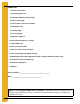
Check List 1. All wire connections 2. Spark plug gap 0.125 3. Pipe train tightness and gas leaks 4. Flame sensor tight 5. Fuse in place, extra fuse provided 6. Time delay reset 7. Indicator light 8. Pressure gauge 9. Regulator adjusted 10. Shut off valve operates correctly 11. Vapor High-Limit 12. Unit cycles ON to OFF 13. Heat rise even across transition 14. Unit cycles High-Low (High-Low only) 15. Modulating valve holds temperature within 1 degree (modulating units only) 16.
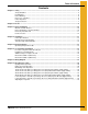
Table of Contents Contents Chapter 1 Safety .................................................................................................................................................. 5 Safety Guidelines ............................................................................................................................... 5 Fuel Warning ...................................................................................................................................... 6 Power Warning ......
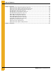
Table of Contents Chapter 9 Parts List .......................................................................................................................................... 26 DW Propane Vapor High-Fire Pipetrain Components ...................................................................... 27 DW Propane Vapor High-Low Fire Pipetrain Components .............................................................. 28 DW Propane Vapor Modulating Pipetrain Components .........................................
1. Safety Safety Guidelines This manual contains information that is important for you, the owner/operator, to know and understand. This information relates to protecting personal safety and preventing equipment problems. It is the responsibility of the owner/operator to inform anyone operating or working in the area of this equipment of these safety guidelines. To help you recognize this information, we use the symbols that are defined below. Please read the manual and pay attention to these sections.
1. Safety Fuel Warning Do not use propane tanks which have previously been used for ammonia unless they have been purged according to procedures of the National LP Association. Be sure fuel supply system complies with all local codes for LP gas installations. DO NOT USE FLAME FOR LEAK TESTING. Power Warning Be sure power is disconnected and locked out before installation. Failure to do so may cause serious injury or death. IMPORTANT: Heater must be interlocked with fan for safe operation.
1. Safety Safety Instructions Our foremost concern is your safety and the safety of others associated with this equipment. We want to keep you as a customer. This manual is to help you understand safe operating procedures and some problems which may be encountered by the operator and other personnel. As owner and/or operator, it is your responsibility to know what requirements, hazards and precautions exist, and to inform all personnel associated with the equipment or in the area.
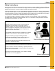
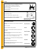
1. Safety Install and Operate Gas-Fired Equipment Properly Fuel supply should be installed by a qualified gas technician and must meet local and state codes for gaseous fuel supplies. Disconnect and lock out all fuel sources before servicing equipment. Explosive Gases Prepare for Emergencies Be prepared if fire starts. Keep a first aid kit and fire extinguisher handy. Keep emergency numbers for doctors, ambulance service, hospital and fire department near your telephone.
2. Decals The GSI Group recommends contacting your local power company, and having a representative survey the installation so the wiring is compatible with their system, and adequate power is supplied to the unit. If a decal is damaged or missing, contact: GSI Decals 1004 E. Illinois St. Assumption, IL. 62510 Phone: 217-226-4421 A free replacement will be sent to you.
3. Heater Installation Machine to Earth Ground It is very important that a machine to earth ground rod be installed at the fan. This is true even if there is a ground at the pole 15' away. This ground needs to be as close to the fan as possible, but no more than 8' away. The ground rod should be connected to the fan control panel with at least a #6 solid bare copper ground wire, or in accordance with local requirements. The machine to earth ground provides additional safety if there is a short.
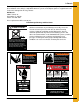
3. Heater Installation Proper Installation of the Ground Rod (Continued) 5. Connect the bare copper ground wire to the rod with the proper ground rod clamp. 6. Connect the bare ground wire to the fan control boxes with a grounding lug. (See Figure 3B.) 7. Ground wire must not have any breaks or splices. Insulated wire is not recommended for grounding. Figure 3B Use a #6 or approved size bare copper ground wire.
3. Heater Installation Fuel Connection Liquid Propane Models 1. LP models are designed to run on liquid propane with liquid draw from the propane tank. Avoid using propane supply tanks that have been used for vapor draw for long periods of time. When using liquid draw systems any moisture that may be present in tank or lines may freeze when system is used in cold weather. To avoid this situation, purge the system with methanol. 2.
4. Installation Heater Specifications Centrifugal Heater Specifications High-Temperature Model Low-Temperature Model BTU Rating 4000000 500000 Weight 145 135 Maximum Fuel Flow (GPH) 43 N/A Orifice Size 0.25 N/A Minimum Operating Pressure 3 N/A Maximum Operating Pressure 30 N/A Minimum Line Size 3/8" N/A Maximum Fuel Flow (CFH) 1590 210 Orifice Size 0.25 0.
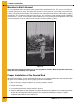
4. Installation Plenum Thermostat Mounting (Continued) Figure 4A Plenum Thermostat Mounting on Bin Wall Transition High-Limit Installation 1. Mark location on transition one (1) foot up from the bottom (entrance collar) and centered in the transition. 2. Drill or knock out 7/8" diameter hole on marked location. 3. Install transition High-Limit using supplied self-drilling screws. Figure 4B The transition connecting the heater to the bin with the plenum thermostat in place.
5. Bin Configuration Figure 5A IMPORTANT: When mounting two (2) heaters on a bin it is imperative that they be situated as in above Figure 5A. Plenum thermostat must be to the right of master heater and master heater must be to the right of slave heater. Operating Temperature Table IMPORTANT: Do not exceed plenum temperatures listed in table. Low-Temperature Batch High-Temperature Batch Dry No Stirring High-Temperature with Stirring Continuous Flow (Recirculating) Corn 5°-20° Above Ambient Temp.
6. Second Heater Installation For Units Using HF-7318 Control Board Two (2) Deluxe heaters may be connected to one (1) grain drying system and wired so they cycle together. One (1) of the heaters should have a thermostat connected to it as per the installation instructions. That heater will be referred to as the master. The other heater (without the thermostat) will be referred to as the slave. Installation for Standard Units 1. Install relay base (TD-100283) in master heater control box. 2.
6. Second Heater Installation Electrical Installation (230V Fans) 1. Connect power cord to fan control box. 2. Make field connections of wires in fan box as shown in Figure 6B. 3. Connect deluxe thermostat control (optional) in heater box as shown in Figure 6B. IMPORTANT: Heater must be interlocked with fan for safe operation. IMPORTANT: Thermostat must be installed for safe operation.
6. Second Heater Installation Electrical Installation (460V Fans) 1. Connect power cord to fan control box. 2. Make field connections of wires in fan box as shown in Figure 6C. 110V power supply or 0.5 KVA 460V to 110V transformer must be used to supply power for heater. 3. Connect deluxe thermostat control (optional) in heater box as shown in Figure 6B on Page 17. IMPORTANT: Heater must be interlocked with fan for safe operation. IMPORTANT: Thermostat must be installed for safe operation.
7.
8. Operating Procedure Cycling Heater Operation 1. Thermostat must be wired into heater control box for heater to operate. 2. Open all manual shut off valves to heater unit. 3. Start fan. This will supply power to heater. 4. Turn thermostat dial to its highest setting. 5. Turn toggle switch ON. 6. Heater should now be lit. If not check to see that all gas is ON. 7. Set thermostat to desired setting (see deluxe thermostat manual for adjusting deluxe thermostat control.) 8.
8. Operating Procedure Modulating Valve Operation 1. The modulating valve regulates gas flow through the heater based on sensing unit in the plenum, and maintains a constant drying air temperature. 2. The sensing bulb of the modulating valve should be mounted through the bin wall with the side reading “top” up. The bulb reacts to temperature. It changes the amount of gas (increase or decrease), burning warmer or cooler depending on the position of the valve SET POINT.
8. Operating Procedure 10 HP-15 HP Units BTUs per Gauge Pressure (PSI) Propane Models (Approximate) High-Temperature 10 HP-15 HP 7/32" (0.
8. Operating Procedure 20 HP-40 HP Units BTUs per Gauge Pressure (PSI) Propane Models (Approximate) High-Temperature 20 HP-40 HP 5/16" (0.
8. Operating Procedure 20 HP-40 HP Units BTUs per Gauge Pressure (PSI) Natural Gas Models (Approximate) High-Temperature 20 HP-40 HP 15/32" (0.469") Orifice Operating Pressure (PSI) All Models 1 2 3 4 5 6 7 1597824 2266320 2770656 3195648 3573216 3919776 4234416 Gauge Pressure (PSI) Required to Maintain Temperature (Approximate) (20 HP-40 HP High-Temperature Natural Gas Units Only) Heat Rise (°F) Fan Model Static Pressure 20 HP 25 HP 30 HP 40 HP 60 80 100 120 140 160 180 2" 0.
8. Operating Procedure Adjusting the Vaporizer 1. Vaporizer should be adjusted so the vapor pipetrain runs warm to the touch (100°F-120°F). 2. Loosen 5/16" bolt on adjustment bracket. 3. Swivel vaporizer away from flame if running too hot, closer to flame if too cold. 4. Move vaporizer only 1" at a time and allow a few minutes for temperature to equalize. 5. Tighten 5/16" bolt and watch heater run for several minutes to verify adjustment.
9. Parts List 1. DW Propane Vapor High-Fire Pipetrain Components 2. DW Propane Vapor High-Low Fire Pipetrain Components 3. DW Propane Vapor Modulating Pipetrain Components 4. DW NG High-Fire Pipetrain Components 5. DW NG High-Low Fire Pipetrain Components 6. DW NG Modulating Pipetrain Components 7. DW LP High-Fire Pipetrain Components 8. DW LP High-Low Pipetrain Components 9. DW LP Modulating Pipetrain Components 10. 40 HP DW High-Temperature Heater Parts 11. 40 HP DW Low-Temperature Heater Parts 12.
9.
9.
9.
9.
9.
9.
9.
9.
9.
9.
9.
9.
9.
9.
Limited Warranty The GSI Group, LLC. (“GSI”) warrants products which it manufactures to be free of defects in materials and workmanship under normal usage and conditions for a period of 12 months after sale to the original end-user or if a foreign sale, 14 months from arrival at port of discharge, whichever is earlier.
This equipment shall be installed in accordance with the current installation codes and applicable regulations which should be carefully followed in all cases. Authorities having jurisdiction should be consulted before installations are made. GSI Group 1004 E. Illinois St. Assumption, IL 62510-0020 Phone: 1-217-226-4421 Fax: 1-217-226-4420 www.gsiag.