Series 2000 Downwind Heater Downwind Series 2000 Centrifugal Heater Installation And Operating Instructions MODEL # CH__ - __ __ - __ __ - 2 __ (HIGH) MODEL # CL__ - __ __ - __ __ - 2 __ (LOW) Owner's Manual PNEG-824 1
Series 2000 Downwind Heater THIS EQUIPMENT SHALL BE INSTALLED IN ACCORDANCE WITH THE CURRENT INSTALLATION CODES FOR GAS BURNING APPLIANCES AND EQUIPMENT, CAN1-B149.1 AND B149.2, OR APPLICABLE PROVINCIAL REGULATIONS WHICH SHOULD BE CAREFULLY FOLLOWED IN ALL CASES. AUTHORITIES HAVING JURISDICTION SHOULD BE CONSULTED BEFORE INSTALLATIONS ARE MADE.
Series 2000 Downwind Heater CHECKLIST _____ 1. Check all wire connections _____ 2. Spark plug and flame sensor tightness set plug gap to 1/8" _____ 3. Check plug in terminal strips on back of circuit board to be sure they are plugged into proper position. _____ 4. Software settings correct for type of heater (hi-low, on-off) _____ 5. Dip switch settings correct for heater model (slave, master) _____ 6. Most current software version installed _____ 7. Turn heater toggle switch on.
Series 2000 Downwind Heater 4
Series 2000 Downwind Heater TABLE OF CONTENTS Safety Series 2000 Heater Installation High Temperature Heater Specifications Low Temperature Heater Specifications Temperature Sensor Box Transition Hi-Limit Installation Bin Configuration/Operating Temperature Table Heater Unit Wiring Secondary Heater Unit Wiring Machine To Earth Ground Proper Installation Of The Ground Rod Previously Installed Units Fuel Connection For Liquid Propane Models Fuel Connection For Propane Vapor Models Fuel Connection For Natura
SAFETY Series 2000 Downwind Heater SAFETY FIRST General Safety Statements The GSI Group Inc’s Principal concern is your safety and the safety of others associated with grain handling equipment. We want to keep you as a customer. This manual is to help you understand safe operating procedures and some problems which may be encountered by the operator and other personnel.
SAFETY Series 2000 Downwind Heater Roof Damage Warning And Disclaimer GSI DOES NOT WARRANT ANY ROOF DAMAGE CAUSED BY EXCESSIVE VACUUM OR INTERNAL PRESSURE FROM FANS OR OTHER AIR MOVING SYSTEMS. ADEQUATE VENTILATION AND/OR "MAKEUP AIR" DEVICES SHOULD BE PROVIDED FOR ALL POWERED AIR HANDLING SYSTEMS. GSI DOES NOT RECOMMEND THE USE OF DOWNWARD FLOW SYSTEMS (SUCTION). SEVERE ROOF DAMAGE CAN RESULT FROM ANY BLOCKAGE OF AIR PASSAGES.
SPECIFICATIONS Series 2000 Downwind Heater Centrifugal Heater Specifications Hi-Temp Hi-Temp Lo-Temp Model 10-15HP 20-40HP All units BTU Rating 2225000 4500000 500000 Weight 145 145 135 Maximum Fuel flow (GPH) 24 49 N/A Orifice size 0.2188 0.3125 N/A Mod Valve Bypass Orifice Blue Aluminum Yellow Minimum operating pressure 1 1 N/A Maximum operating pressure 15 15 N/A Minimum line size 3/8" 3/8" N/A Maximum Fuel flow (CFH) 931 1898 210 Orifice size 0.2188 0.
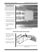
Series 2000 Downwind Heater HEATER INSTALLATION PLENUM TEMPERATURE SENSOR MOUNTING The plenum temperature sensor is the white PVC junction box with bolt extending from outside attached by a cord to the fan/heater control box. 1. 24" to the right side of the transi tion, drill one 3/8" hole in the cen ter of the plenum in a valley on the bin sidewall. 2. Insert the probe through the hole. 3. Position the housing so that the tabs are vertical, and the cord exits the housing horizontally. 4.
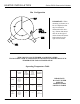
HEATER INSTALLATION Series 2000 Downwind Heater Bin Configuration IMPORTANT! When mounting (2) heaters on a bin it is imperative that they be situated as illustrated in this drawing. Plenum thermostat must be to the right of master heater and master heater must be to the right of slave heater. THIS TABLE IS NOT INTENDED AS A DRYING GUIDE. IT SHOULD BE USED AS A REFERENCE FOR SETTING MAXIMUM PLENUM TEMPERATURE FOR SAFE OPERATION.
HEATER INSTALLATION Series 2000 Downwind Heater Wiring Heater Unit 1. Be sure fan unit is installed and wired to meet local codes. Be sure equipment is well grounded (see page 10). 2. A separate neutral is required for 120 volt heater circuit in 220 volt 1PH and 3PH fan units. For 460 volt fan units a separate 120 volt power supply or transformer is required. 3. Run 5-wire black cord from heater unit to fan unit and se- Figure 2: Wiring diagram for the fan and heater unit. cure to fan. shuts down.
HEATER INSTALLATION Series 2000 Downwind Heater Machine To Earth Ground It is very important that a machine to earth ground rod be installed at the fan. This is true even if there is a ground at the pole 15 feet away. This ground needs to be as close to the fan as possible, but no more than 8 feet away. The ground rod should be connected to the fan control panel with at least a #6 solid bare copper ground wire, or in accordance with local requirements.
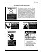
HEATER INSTALLATION Series 2000 Downwind Heater IMPORTANT! Do not use pro- Standard electrical safety prac- WARNING tices and codes should be used when working with a heater. Refer to the National Electric Code Standard Handbook by ALWAYS DISCONNECT AND LOCK OUT POWER BEFORE WORKING ON OR AROUND HEATER pane tanks that have previously been used for ammonia unless they have been purged according to procedures of the National L.P. Association. the National Fire Protection Association.
HEATER INSTALLATION Series 2000 Downwind Heater Figure A Installing Optional Humidity Sensor 1. Humidity sensor should be mounted 6-8" right of the airswitch/temperature sensor box. See Figure A. 2. Using sensor as a guide drill or knock-out 7/8" diameter hole in the center of the plenum on the bin sidewall. If you are using sensor to sense drying air humidity. Figure B 14 3. Insert pipe nipple from sensor housing through hole in side wall and use selfdrilling screws to mount to sidewall.
Series 2000 Downwind Heater OPERATING PROCEDURE The control panel display showing initial start up. Standard electrical safety practices and codes should be used when working with a heater. Refer to the National Electric Code Standard Handbook by the National Fire Protection Association. A qualified electrician should make all wiring installations. WARNING ALWAYS DISCONNECT AND LOCK OUT POWER BEFORE WORKING ON OR AROUND HEATER Power Up All safety and high limit switches are checked upon power up.
OPERATING PROCEDURE Series 2000 Downwind Heater Normal Operating Displays With Heater Not Running The main display shows the plenum temperature. If the dryer has not been running, the display should show outside temperature. The control is preset at the factory to display temperature in centigrade or fahrenheit. "AIRFLOW" or "NO AIRFLOW" is displayed if air is flowing or not flowing. "RX TX" (receive, transmit) is displayed if multiple heaters are connected.
Series 2000 Downwind Heater OPERATING PROCEDURE Starting The Dryer After heater power is turned on, the fan must be turned on. Attempting to start the dryer without the air switch indicating there is airflow will cause an airflow alarm to go off when the start switch is depressed. The airflow alarm is simply the entire display going blank, and the "NO AIRFLOW" message flashing for a few seconds. The display must show "AIRFLOW" before the dryer can be started.
OPERATING PROCEDURE 16. When the burner ignites the display should read "HI-FLAME " at the left of the display. Loosen the nut on the main regulator and turn screw in, to increase pressure and out to decrease pressure. The pressure gauges should be set at 10-15 lbs. for LP units, or 4-6 lbs.. for natural gas units. (use the charts on the following pages to set pressure) 17. Press the "PROGRAM TEMPERATURE" button to change the high limit set point. Press it again to change the "CYCLE SET POINT".
OPERATING PROCEDURE Series 2000 Downwind Heater 10-15 hp Units BTUs Per Gauge Pressure (psi) PROPANE MODELS (Approximate) High Temperature 10-15hp 7/32" (0.
OPERATING PROCEDURE Series 2000 Downwind Heater 20-40 hp Units BTUs Per Gauge Pressure (psi) PROPANE MODELS (Approximate) High Temperature 20-40hp 5/16" (0.
OPERATING PROCEDURE Series 2000 Downwind Heater 20-40 hp Units BTUs Per Gauge Pressure (psi) NATURAL GAS MODELS (Approximate) High Temperature 20-40hp 15/32" (0.469") Orifice OPERATING PRESSURE (psi) 1 ALL MODELS 2 3 4 5 6 7 1,597,824 2,266,320 2,770,656 3,195,648 3,573,216 3,919,776 4,234,416 Gauge Pressure (psi) Required to Maintain Temperature (Approximate) (20-40 hp High Temperature Natural Gas Units Only) Heat Rise (°F) Fan Static Model Pressure 60 80 100 120 140 160 180 2" 0.
OPERATING PROCEDURE Series 2000 Downwind Heater Lo-Temp Units BTUs Per Gauge Pressure (psi) PROPANE MODELS (Approximate) Low Temperature All hp 7/64" (0.109") Orifice OPERATING PRESSURE (psi) ALL MODELS 2 4 6 8 10 12 14 15 203,405 287,160 351,771 409,203 457,063 497,744 538,425 555,176 Lo-Temp Units BTUs Per Gauge Pressure (psi) NATURAL GAS MODELS (Approximate) Low Temperature All hp 5/32" (0.
Series 2000 Downwind Heater OPERATING PROCEDURE Adjusting The Vaporizor 1. Vaporizer should be adjusted so the vapor pipetrain runs warm to the touch (100°-120°F). 2. Loosen 5/16" bolt on adjustment bracket. 3. Swivel vaporizer away from flame if running too hot, closer to flame if too cold. 4. Move vaporizer only 1" at a time and allow a few minutes for tem perature to equalize. 5. Tighten 5/16" bolt and watch heater run for several minutes to verify adjustment.
OPERATING PROCEDURE The limits are continuously checked during the drying operation. A limit switch open or any other error condition will cause the dryer to shutdown, and the fan will be shutdown. If a limit opens, or an error condition occurs during drying, the control will lockup in the error display mode. Power must be shut off and back on to the control to clear the error condition-even if the error or limit that caused the shutdown has been corrected.
Series 2000 Downwind Heater OPERATING PROCEDURE On hi-lo units when the unit reaches cycle set point, the flame will switch to lo-flame and unit will not cycle back to hi-flame until (Set Point minus Temperature Differential) is reached. Temperature differential would normally be set for 10-15 degrees F for high temp units, and 2-5 degrees F for lo-temp units. Humidity Differential--The upper right cursor is flashing indicating the mode.
OPERATING PROCEDURE Series 2000 Downwind Heater Modulating Valve Operation 1. The modulating valve regulates gas flow through the heater based on sensing unit in the plenum, and maintains a constant drying air temperature. 2. The sensing bulb of the modulating valve should be mounted through the bin wall with the side reading "top" up. The bulb reacts to temperature. It changes the amount of gas (increase or decrease), burning warmer or cooler depending on the position of the valve SET POINT.
Series 2000 Downwind Heater Configuration Dip Switches (Normally Done At GSI) These switches are used to configure the heater control for various types of heaters. Stand alone heater with no slaves, all dip switches in the off state. FACTORY CONFIGURATION Multiple heaters connected together through the serial link. Master with one slave-dip switch 7 on/all others off. Slave #1-dip switch one and three on/all others off. Master with two slaves-dip switch 8 on/all others off.
ERROR CONDITIONS Series 2000 Downwind Heater Limit Switches The following limit switch errors light up individually on the heaters LCD screen: PLENUM, HOUSING, VAPOR, TEMP HI LIMIT. Note: When a shutdown does occur due to an error condition, the amount of time elapsed since the shutdown can be viewed by pressing the down arrow switch (up to 218 Hours).
HEATER SERVICE Series 2000 Downwind Heater All Airstream heaters are constructed of durable weather-resistant materials, so a minimum amount of service should be required; however before the unit is started for the first time each season there are a few items that need to be checked out. All damaged parts should be repaired or replaced. 1. Disconnect and lock out power to fan and heater. Open control box lid and inspect all components for moisture, vibration or rodent damage.
WIRING DIAGRAM 30 Series 2000 Downwind Heater
Series 2000 Downwind Heater NOTES ______________________________________________________________________________________________________________ _____________________________________________________________________________________________________ __________________________________________________________________________________________________________ ______________________________________________________________________________________________________ _____________________________________________________
WARRANTY Series 2000 Downwind Heater THE GSI GROUP, INC. ("GSI") WARRANTS ALL PRODUCTS MANUFACTURED BY GSI TO BE FREE OF DEFECTS IN MATERIAL AND WORKMANSHIP UNDER NORMAL USAGE AND CONDITIONS FOR A PERIOD OF 36 MONTHS AFTER RETAIL SALE TO THE ORIGINAL END USER OF SUCH PRODUCTS. GSI'S ONLY OBLIGATION IS, AND PURCHASER'S SOLE REMEDY SHALL BE FOR GSI, TO REPAIR OR REPLACE, AT GSI'S OPTION AND EXPENSE, PRODUCTS THAT, IN GSI'S SOLE JUDGMENT, CONTAIN A MATERIAL DEFECT DUE TO MATERIALS OR WORKMANSHIP.
Series 2000 Downwind Heater 33
Series 2000 Downwind Heater 1004 E. Illinois St.