INTERNATIONAL ALASKAN ® MARK IV CHAIN SAW MILL Innovative Tools For Chainsaw Milling & Sharpening Since 1957
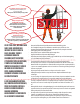
Use adequate ear and eye protection* Utilisez des protections adéquates pour les yeux et les oreilles Utilice protección adecuada para ojos y oídos* STOP! Always wear gloves when working with a chainsaw Portez toujours des gants lorsque vous travaillez avec une tronçonneuse Lleve siempre guantes al trabajar con una motosierra Secure loose clothing, use chaps* and appropriate footwear Utilisez des protections adéquates pour les yeux et les oreilles Colóquese de forma segura la ropa holgada, utilice protec
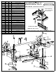
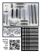
ITEM NO. 1 PART NO. 0882F 2 0884F 4 3 0886F 4 QTY.
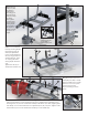
24 13 27 26 8 22 12 14 19 25 18 3 2 16 6 15 11 9 4 23 7 5 1 Familiarize yourself with mill components by laying out as shown. SCAN THE QR CODE TO SEE A VIDEO OF THE ASSEMBLY PROCESS 10 21 20 17 10 ITEM NO. 1 PART NO. 0882F QTY.
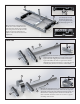
1a Attach handle boss (1) to end bracket (8) using socket screws (2) and collar lock washers (3). Tighten with hex head Allen wrench (27). Repeat with other end bracket. Make sure slot in handle boss faces the outside, as shown. Note: (2b) should be left somewhat loose. This is your end bracket assembly (8a). 8a 1 2b 3 27 8 2 2a Attach tie bar (17), and handle (25) to on-off bar (19) using two carriage bolts (9), two lock washers (23) and one hex nut (6) and one coupling nut (15).
21 5 4 4b Slide U bolt (4) through post clamps (5) and end bracket (8a) and loosely secure using flat washers (7) and coupling nut (15). 2 4a Slide handle (21) through holes in handle boss. Secure handle at thrust end, flush with outside edge of handle boss using socket screws (2). The same applies to the nose end but do not tighten screws. This will allow for later adjustment.
a Attach nose end post (22a) assembly to end bracket by sliding post through u-bolt and post clamp assembly (8a). Tighten coupling nuts (item 15) after setting depth post height at 4”. Repeat on thrust end (12a, see photo on right). 8a 4 8a 15 7b Tighten coupling nuts (15) on U bolt(4) to secure depth posts to bracket. 22a 8a Mill is now assembled. Finish by inserting handle plug and post plug (16 and 18) to adjustment posts (12 and 22)and handle (21). Set grip (24) over small handle (25).
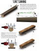
‘LIVE’ SAWING Step 1: Arrange first cut guide on log (fig A). Slabbing bracket system is shown, but principle is similar if using EZ Rails. For best results, measure the distance from the center growth ring (X)on the narrow end, and mark corresponding distance on wide end of the log (fig C). Set mill on first cut guide as shown (fig B). Starting from the wide end, begin your first cut. The first cut will look like a wedge (fig C) A X X C B D Step 2: Remove wedge created by first cut.
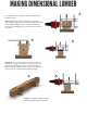
MAKING DIMENSIONAL LUMBER G To make dimensional lumber, make your first cut as shown in step 1. Step 3: Once first cut has been made, set mill to desired depth (fig G). This will be the width of the final beam. When making second cut, make sure to use wedges so that weight of log does not pinch the bar and chain. H I Step 4: Once second cut has been made, rotate log 90 degrees. Using a carpenter’s square, set first cut system at right angles to cuts one and two (fig H).
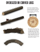
OVERSIZED OR CURVED LOGS If your log is longer than the EZ rails or 2x4s used with the slabbing brackets, or if the log is curved, use the following method to make your first cut. You will need a flat plank, 6-inch long spikes, some heavy duty cord, and a spirit level. Drive spikes along length of log. Secure the cord on the spikes and use spirit level to ensure they are level. Once spikes are level along the full length of the log, set the board on top of the spikes.
INSTRUCCIONES DE MONTAJE DE G778 1a Acoplar el mango saliente (1) al soporte de extremo (8) con un tornillo de cabeza hueca (2) y con una arandela de presión (3). Apretar con una llave Allen de cabeza hexagonal (27). Repetir con el otro soporte de extremo. Nota: (2b) se debe dejar algo suelto. El mango saliente debe estar orientado hacia afuera, tal como se muestra. Este es su montaje del soporte extremo (8a).
INSTRUCTIONS DE MONTAGE G778 1a Fixer le bossage de la poignée (1) au support d’extrémité (8) à l’aide de la vis à tête creuse (2) et de la rondelle-frein épaisse (3). Serrer à l’aide d’une clé Allen six pans (27). Recommencer l’opération avec tous les autres supports d’extrémité. S’assurer que la fente dans l’embossage de la poignée se trouve vers l’extérieur, comme cela est illustré. Remarque: (2b) doit être laissé un peu lâche. Voici l’ensemble des supports d’extrémité (8a).