
Product Manual

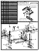

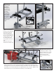

4a Slide handle (21) through holes in
handle boss. Secure handle at thrust
end, ush with outside edge of handle
boss using socket screws (2). The same
applies to the nose end but do not
tighten screws. This will allow for later
adjustment.
4b Slide U bolt (4) through
post clamps (5) and end
bracket (8a) and loosely
secure using at washers
(7) and coupling nut (15).
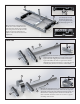
6a Insert two hex head bolts (11) through at washers (7) and
into holes in adjustment post (22). Slide bolts through nose
guard (14) and then through clamping bracket (20). Nuts are
welded to the clamping bracket. Start hex head bolts into
nuts on bottom of bracket. Leave loose so there is a gap for
mounting chain saw bar.
5a Insert two Hex head bolts (11) through at washers
(7) then through adjustment post (12) and into clamp-
ing bracket, (13) engaging nuts on bottom of clamp-
ing bracket. Make sure there is a gap for the saw bar.
Adjustment post measurements are on skid side of post
assembly. They face the inside of the sawmill frame.
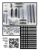
11
11
12
22
11
11
7
7
20
14
7
7
13
21
5
4
15
7
2
12a
22a
THRUST END
NOSE END
THRUST
END