
Assembly Instructions


5
INSTALLATION AND ASSEMBLY
ALWAYS unplug this replace heater before assembly, cleaning, or relocating.
Failure to do so could result in electric shock, re, or personal injury.
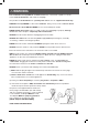
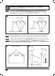
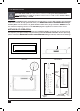
STEP 1: Find a safe location.
Minimum clearance
on each side: 20".
Minimum clearance below:
20". (Wall mount only).
Minimum clearance above:
39.5".
Minimum clearance from the front:
36".
Choose a location near an outlet so
an extension cord is not required.
DO NOT position the unit
directly below a power outlet.
The Drywall Anchors(C) included with this replace are for use ONLY with a wood
framed wall covered in drywall (sheet rock). For concrete walls, cinder blocks, or
other wall types, consult a pro
fessional for the best attachment methods.
NOTICE
Minimum 39.5"
Minimum 20"
(Wall mount only)
20" 20"
1
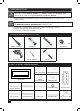
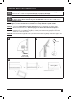
STEP 2: Locate the wall studs using an electronic stud nder.
STEP 2a: If two studs are available, drill 1 hole in each using 1/4” drill bit. Drill third and
nal hole in the middle of the two studs.
STEP 2b: If only 1 stud is available, use stud as center and drill 2 holes on either side of stud
(each hole should be 13.4” apart from another).
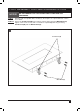
STEP 3: With a hammer, tap the Drywall Anchors(C) carefully into the hole(s) until they are ush
with the drywall surface. Use care to avoid damaging the drywall with the hammer.
2
Studs
Drywall Anchors(C)
2a 2b
Two Studs
One Stud
8"
13.4"
8"
3
Drywall Anchors(C)
ALWAYS make sure the unit is unplugged before beginning assembly! NEVER move or
clean the heater, or change the bulb, while it is plugged in.
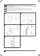
If three stud are available, use stud as center and drill 2 holes on either side of stud
(each hole should be 16” apart from another).
13.4"
16"
16"