
Instructions / Assembly


Door Hardware
Installation Instructions
Handleset - Single Cylinder Version
Carefully unpackage all components and place them within easy
reach. Find Figure #1A and Figure #1B (exploded drawings
with parts listing) at the back of these instructions. Figure #1A
is for a longplate style interior, and Figure #1B is for a rosette
(round) style interior. Use Part #19 to determine which of these
two figures is appropriate for your installation and discard the
other to avoid confusion. Place the appropriate Figure #1 for your
installation beside the components for easy reference. For the
balance of these instructions, we will only refer to this exploded
drawing as Figure #1.
You will need a #2 Phillips screwdriver for installation of your
new doorsets. If the door is not pre-drilled, you will also need a
2-1/8” hole saw, a 7/64” drill bit, 7/32” drill bit, 5/16” drill bit,
7/8” drill bit, and 1” drill bit (spade or forstner style), a chisel, a
pencil and an awl (or nail). If your door is pre-drilled start at Step
2.
Step 1
Door Preparation
A) Find the Entry Door Preparation Templates. Determine
if your door is beveled (see illustration on templates). If so,
choose the appropriate Entry Door Preparation Template and
fold along line B to match the illustration. If your door is
not beveled, choose the appropriate Entry Door Preparation
Template that will mount on the outside of your door and
fold along line B.
B) Carefully position the template on the outside of the door
so that the line marked A is approximately 36”-38” from the
floor, depending on preference of doorknob height. Make
sure that the corner of the door is lined up with the fold (line
B) and tape the template to the door. IMPORTANT—If your
door is prepped with a 2-1/8” hole for the doorknob, match
line A with the center of the existing doorknob hole.
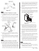
C) Determine if your “backset” is 2-3/8” or 2-3/4”. If your
door is prepped for a lock, the backset is the distance from
the edge of the door to the center of the cross-bore hole
(see Figure #2). If your door is not prepped, then find the
handleset latch (Figure #1, Part #14). Measure the distance
from the flange to the center of the star-shaped hub. The
distance will be slightly under 2-3/8” or 2-3/4” to allow for
adding a faceplate. See Figure #2. If your backset is 2-3/8”,
use line C on the template. If your backset is 2-3/4”, use line
D.
D) Using the awl (or a nail), mark the three intersecting points
on the template as indicated below, making sure the door is
clearly marked:
2-3/8″ Backset
or
2-3/4″ Backset
Where lines E & C cross Where lines E & D cross
Where lines A & C cross Where lines A & D cross
Where lines F & C cross Where Lines F & D cross
E) Measure the thickness of your door. Most exterior doors
are 1-3/4”, 2” or 2-1/4” thick. Once you have measured the
thickness, mark the points on the edge of the door where lines
A and E intersect with your appropriate door thickness line.
F) With the template still on the door, close the door. Using
a pencil, lightly mark on the door jamb where lines A and
E meet the jamb. Find the Door Jamb Template and fold
along line BB. Once the template has been folded, place it
against the door jamb so that the folded edge matches up with
where the edge of the door sits when closed. Match lines AA
and EE to the marks you made from lines A and E. Once
aligned, tape the Door Jamb Template to the door jamb. Find
the four points where lines 1, 2, 3, & 4 cross the correct door
thickness. Using the awl (or a nail), mark these four points on
the jamb.
G) Verify that all marks can be clearly seen on the door and door
jamb and remove both templates.
H) Using Figure #
3 and the marks made in Step 1D as a
reference, drill the two 2-1/8” cross-bore holes using a hole
saw. IMPORTANT—To avoid damaging the door, drill from
one side until the pilot bit comes through the door. Then
finish drilling from the other side, using the pilot hole as your
guide. IMPORTANT—Always drill as straight or level as
possible to ensure proper door preparation.
I) Using Figure #
3 as reference and the marks made in Step 1E,
drill the two 1” edge-bore holes. Make sure that you drill a
full 3-7/8” deep for 2-3/8” backset, or 4-3/8” deep for a 2-
3/4” backset, which will extend beyond the cross-bore holes.
1-800-522-7336
For
Assistance
Call:
8 am - 5 pm, Monday - Friday, MST
or visit our Website at: www.grandeur-nw.com
Flange
Star-shaped hub
Figure #2
Figure #3
Page 1- PK161