
Instructions / Assembly


C) Installthe3/4”latch&strikewoodscrews(Part#3)tohold
thedeadboltlatchanddeadboltfaceplateinplace.
Step 5
Install the “Outside” Half of the Deadbolt
A) Using Figure #1 for reference, gather together the cylinder
assembly(Part#4),spinring(Part#5A),theoutside
escutcheon(Part#5B),thedeadboltadaptorplate(Part#7)
andtwo1-1/4″machinescrews(Part#8).
B) Placethespinringoverthecylinderdriverbar(Part#4A)
end of the cylinder, making sure that the narrower edge of
the spin ring is closest to the key hole end of the cylinder.
Insertthecylinderthroughthespinringandescutcheonto
maketheoutsideassemblycomplete,seeFigure #5.
C) Fromtheoutsideofthedoor,insertthecylinderdriverbar
(Part#4A)throughthe“+”inthelatchhousing,making sure
that the driver bar is oriented vertically with the latch bolt
extending from the edge of the door.
D) Makesurethatthecrossboreholewillbecompletelycovered
bytheoutsideescutcheonandthattheGrandeurlogois
oriented correctly.
E) Ontheinsideofthedoor,placetheadaptorplatesothatthe
beveledscrewholesfaceawayfromthedoorandlineupwith
thecylinderposts.Screwonthetwo1-1/4″machinescrews
toholdtheoutsideassemblyinplace,seeFigure #6. Do not
tighten yet.
F) Align the outside escutcheon and cylinder with the door
edgeandsnugthetwo1-1/4″machinescrewsdown.Donot
overtighten.
G) Usingthekey,unlockandre-lockthelatchtomakesurethat
theactionissmooth.Ifthescrewshavebeenovertightened,
thelatchmaybind.Oncetheactionisacceptable,moveonto
Step6.
Step 3
Mortise for the Faceplate
A) Using Figure #1forreference,ndthefaceplate(Part#2).
Ontheedgeofthedoor,centerthefaceplateoverthenewly
drillededgeborehole,sothattheD-shapedholeinthe
faceplateiscenteredoverthe1″edgeborehole.Alignthe
faceplate so that the edges are parallel to the edges of the door
and roughly centered side-to-side. Mark around the faceplate
with a pencil and remove from door.
B) Using the chisel, score the outline of the faceplate. Next,
chiselawaythematerialwithintheoutlinetoadepthof1/8″.
Whenyouaredone,youshouldbeabletoinsertthelatch
(Part#1)intotheedgeborehole,placethefaceplateoverthe
latchtongue(Part#1a),andhavethefaceplatebeushwith
the edge of the door.
C) Again, using the faceplate as a template and the awl as a
marking tool, mark for the two screw holes that will hold the
faceplate on the door. Remove the faceplate from the door
toavoidmarringthenish.Then,drillthetwoscrewholes
usinga7/64″drillbit.Makesuretheholesaredrilledatleast
1″deep.Havingtoosmallortooshallowaholecancausethe
screws to shear off.
Installing Your Lock
Step 4
Install the Latch
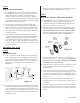
A) InsertascrewdriverintothelatchhousingandextendtheA)
Insertascrewdriverintothedeadboltlatchhousing(Part#1)
andextendthedeadbolt.Insertthedeadboltlatchintothe
edgeborehole,makingsurethatthe“+”isorientedtowards
theloweredgeorbottomsideofthedeadboltlatch,see
Figure #4.
B) Addthedeadboltfaceplateoverthedeadboltlatchandmake
surethatitcansitushinthemortisedoutarea.Note:Some
doors come prepared with rounded corners in the mortised-
outarea.Ifyourdoorispreparedlikethis,simplyuseachisel
tosquareoffthecornerssothatthefaceplateliesushwith
the edge of the door.
Page2-PK147
Figure #4
Figure #5
hv/RIENTEDONTHE
LOWEREDGE
$EADBOLT,ATCH
0ART
%XTENDED
$EADBOLT
0ART!
$EADBOLT
&ACEPLATE
0ART
v,ATCH3TRIKE
7OOD3CREWS
0ART
%DGE"ORE
(OLE