
Instructions / Assembly

Step 3
Install the “Outside” Half of the Deadbolt
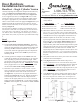
A) Using Figure #1 for reference, gather together the cylinder
assembly (Part #4), spin ring on longplate installations (Part
#5A), the escutcheon (Part # 5 or #5B), the deadbolt adaptor
plate (Part #6), the security ring (Part #16), and two 2-3/4”
machine screws (Part #7). Part #5A is not used or required for
a rosette installation.
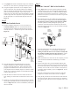
B) Place the spin ring over the cylinder driver bar (Part #4A)
end of the cylinder, making sure that the narrower edge of
the spin ring is closest to the key hole end of the cylinder.
Insert the cylinder assembly through the spin ring and
escutcheon. On the back of the escutcheon, slip the narrow
end of the security ring (Part #16) onto the cylinder assembly
as shown in Figure #5.
C) From the outside of the door, insert the cylinder driver bar
(Part #4A) through the “+” in the deadbolt latch housing,
making sure that the driver bar is oriented vertically with
the deadbolt extending from the edge of the door. If done
correctly, the outside assembly should hold itself in place
temporarily.
D) Make sure that the cross bore hole will be completely covered
by the escutcheon and that the Grandeur logo is oriented
correctly.
E) On the inside of the door, place the deadbolt adaptor plate
(Part #6) so that the beveled screw holes face away from the
door and line up with the corresponding holes on the cylinder
assembly. Screw in the two 2-3/4” machine screws (Part #7)
to hold the outside assembly in place, see Figure #6. Do not
fully tighten yet.
F) Align the escut
cheon and cylinder with the door edge and
snug the two machine screws down. Do not over tighten.
G) Using the key, unlock and re-lock the latch to make sure that
the action is smooth. If the screws have been over tightened,
the latch may bind. Once the action is acceptable, move on to
Step 4.
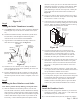
J) Using Figure #3 and the mark made in Step 1D as reference,
drill one 7/32” hole all the way through the door at point M.
K) Using the faceplates (Parts #2 & #15) as templates and a
pencil to mark with, line up the faceplate for the deadbolt
(Part #2) with the top edge-bore hole on the door and lightly
mark a line around the faceplate. Then, using a chisel,
mortise out a 1/8” deep area to allow the faceplate to sit flush
with the edge of the door. Repeat this step with the faceplate
for the latch (Part #15) on the bottom edge-bore hole. See
Figure #
3.
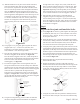
Step 2
Install the Deadbolt Latch
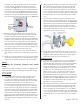
A) Find the Deadbolt Latch (Part #1). Use a screwdriver to
extend the deadbolt (Part #1A). Insert the latch into the
top edge-bore hole, making sure that the latch is oriented
correctly with the “+” on the lower portion of the latch. See
Figure #4.
B) Place the faceplate for the deadbolt (Part #2) over the
deadbolt and make sure that it sits flush in the mortised
out area on the edge of the door. Note: some doors come
prepped with rounded corners in the mortised out area. If
your faceplate does not sit flush, simply use a chisel to square
off the corners so that the faceplate for the deadbolt sits flush
with the edge of the door.
C) Drill the latch screw holes with
7/64” drill bit at least 3/4”
deep. Having too small a hole can cause the screws to shear
off.
D) Install two
3/4” latch & strike wood screws (Part #3) through
the faceplate and deadbolt latch to hold them both in place, as
shown in Figure #4. TIP: for ease of installation, add soap to
the screw threads.
Deadbolt
Latch
(Part #1)
Deadbolt
(Part #1A)
Deadbolt
Faceplate
(Part #2)
3/4” Latch
& Strike
Wood
Screws
(Part #3)
Rotate latch
bolt so curved
surface faces
door jamb.
Latch
Faceplate
(Part #15)
Handleset
Latch
(Part #14)
Latch
Bolt
(Part #14A)
Figure #4
Page 2 - PK161
Figure #5