
Instructions / Assembly
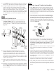

the door is closed, you can cover the end of the bolt with a
light amount of lipstick or similarly visible material. When
you turn the thumbturn, the lipstick will mark the door
jamb. Measuring in from the “door stop trim”, identify the
center mark where the bolt hole needs to be drilled, see
Figure #8.
B) U
sing a 7/8” drill bit, drill two holes centered 5/16” above
and below the center mark. These holes will overlap. Make
sure each one is at least 1-1/8” deep.
C) Clean out the hole (if needed) and insert the dust box (Part
#10). Close the door carefully, making sure not to crush the
dust box. Make sure that the deadbolt and dust box line up.
If not, carefully enlarge the hole as needed.
D) Using the strike plate (Part #13), mark the area to be
mortised out for the dust box (Part #10), the door frame
reinforcer (Part #11), and the strike plate. Use a chisel
to mortise this area 3/16” deep and make sure that once
assembled, the strike plate sits flush to the door jamb.
E) Insert the dust box and place the door frame reinforcer over
the dust box. Using the door frame reinforcer as a guide,
find the holes closest to the outside of the house and drill
two 7/64” x 3” deep holes for the reinforcer screws. See
Figure #8.
F) Install the door reinforcer using the 3” wood screws (Part
#12). Again, check to make sure the deadbolt and reinforcer
line up and that the deadbolt can be locked.
G) Place strike plate over door frame reinforcer and drill two
3/4” deep holes (using the 7/64” drill bit) for the strike plate
and install the strike plate using the 3/4” latch and strike
wood screws (Part #3). Again, check to make sure the
deadbolt, reinforcer and strike plate line up and are flush
with the door jamb and that the deadbolt can be locked.
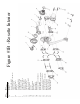
Step 6
Install the Handleset Latch
A) Once your door is prepped for installation, you will need a
#2 Phillips screwdriver, a drill, and a 4” x 7/64” drill bit for
the installation of your new doorsets.
B) Locate the
handleset latch (Part #14) and the anti-rotation
Figure #8
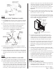
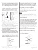
Step 4
Adding the Inside Thumbturn Assembly
A) Using Figure #1 for reference, gather together the thumbturn
assembly (Part #8), and the two 5/8” machine screws (Part
#9).
B) Install the thumbturn assembly such that the cylinder driver
bar (Part #4A) comes through the latch housing and is
inserted into the slot on the back of the thumbturn.
C) Align the holes on the thumbturn assembly with the two
small holes on the adaptor plate. See Figure #7.
D) Install the two 5/8” machine screws, making sure that the
plate is positioned correctly before tightening the screws. Do
not over-tighten the screws.
E) Turn the thumbturn and the key separately to make sure that
the action is smooth. If the screws have been over-tightened,
the latch may bind. Once the action is acceptable, move on to
Step 5.
Step 5
Installing the Door Reinforcer and Strike
Note: If door jamb is already drilled, go to Step 5E below.
A) With the deadbolt in the unlocked position, close the door.
From the inside of the house, turn the thumbturn and identify
where the bolt is contacting the door jamb. Lightly mark this
with a pencil on the door jamb. Note: This should correspond
with the marks made in Step 1F. Hint: If you cannot see the
bolt clearly, or cannot mark the jamb with a pencil because
Figure #7
Page 2 - PK161
Page 3 - PK161
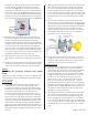
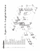
Figure #6