
Instructions / Assembly

B) While holding the handleset in position on the outside of the
door, install the lower mounting screw (Part #23) through
the screw cover adaptor (Part #22) and tighten snugly, but
do not overtighten. If your door thickness is 1-3/4” then the
2-1/4” long screw should be sufficient. Any door thicker than
1-3/4” will require the 2-1/2” screw length to be used. Thread
the mounting screw cover (Part #24) onto the screw adaptor
cover.
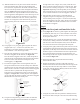
C) Place the rosette assembly in position on the inside of the
door, and insert the rosette mounting screw (Part #20) into the
top screw boss on the back of the handleset, see Figure #10.
Tighten and screw down until almost snug. Insert and tighten
down the second rosette screw into the lower screw boss.
Align the handleset on the outside of the door for appearance
and snug down both rosette screws. Do not overtighten. If
your interior set is a knob, go to Step 8.
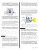
D) If your interior set includes a lever see Figure #11 for lever
orientation. Your lever will only rotate in one direction. It is
designed to rotate downward. If your lever rotates upward,
please call customer service at 1-800-522-7336.
Longplate Version
E) Locate the exterior handleset (Part #17), the mounting plate
(Part #18), the lower mounting screw (Part #23) and the
mounting plate screws (Part #21). Insert one of the mounting
plate screws through the top hole in the mounting plate
and set this aside within easy reach. Note that there are two
lengths of mounting plate screws provided, one 1-1/4” pair,
and one 1-3/4” pair. The majority of doors will use the
shorter screws (1-1/4”), so try these first and only use the
longer screws if the shorter ones do not work. Carefully
place the exterior handleset in position on the outside surface
of the door, such that the spindle (Part #17A) is seated in the
star-shaped hub, see Figure #10. When seated correctly, you
will be able to hold the handleset in place and depress the
thumbpiece to retract the latch bolt.
F) While holding the
handleset in position on the outside of the
door, install the lower mounting screw (Part #23) through
the screw cover adaptor (Part #22) and tighten snugly, but
do not overtighten. If your door thickness is 1-3/4” then the
2-1/4” long screw should be sufficient. Any door thicker than
1-3/4” will require the 2-1/2” screw length to be used. Thread
the mounting screw cover (Part #24) onto the screw adaptor
cover.
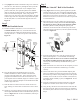
block (Part #27). The anti-rotation block is only used with
a Rosette interior. Insert the anti-rotation block into the
cross bore hole (Figure #3) so that the arrow on the block
is pointing toward the edge of the door. Install the handleset
latch into the edge bore hole (Figure #3), making sure that
it is correctly inserted through the anti-rotation block. When
installed correctly, the star-shaped hub in the latch should be
centered in the hole of the anti-rotation block, see Figure #9.
C) Determine which direction the door will swing when it is
being opened. Rotate the latch bolt (Part #14A) so that the
flat edge of the bolt faces toward the direction the door
swings when being opened (and the round edge towards the
doorjamb). Once oriented correctly, place the faceplate (Part
#15) over the latch bolt, locking the latch bolt orientation.
Note: some doors come prepped with rounded corners in the
mortised out area. If your door is prepped like this, simply
use a chisel to square off the corners so that the faceplate for
the handleset sits flush with the edge of the door.
E) Drill the latch screw holes with 7/
64” drill bit at least 3/4”
deep. Having too small a hole can cause the screws to shear
off.
F) Install two
3/4” latch & strike wood screws (Part #3) through
the faceplate and handleset latch to hold them both in place.
TIP: for ease of installation, add soap to the screw threads.
Step 7
Installing the Exterior Grip-set and Inside
Trim
Determine if you will be installing a rosette or a longplate on the
inside of the door, and go to either Step 7A for Rosettes or Step
7E for Longplates.
Rosette Version
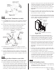
A) Using Figure #1 for reference, gather together the exterior
handleset (Part #17), the inside rosette assembly (Part
#19), the lower mounting screw (Part #23) and the rosette
mounting screws (Part #20). Note that there are two lengths
of rosette screws provided, one 1-1/2” pair and one 2”
pair. The majority of doors will use the shorter screws (1-
1/2”), so try these first and only use the longer screws if the
shorter ones do not work. Insert one of the screws through
the top hole in the rosette assembly and set this aside within
easy reach. Carefully place the handleset in position on the
outside surface of the door, such that the handleset spindle
(Part #17A) is seated in the star-shaped hub of the latch, see
Figure #10. When seated correctly, you will be able to hold
the handleset in place and depress the thumbpiece to retract
the latch.
Page 4 - PK 161
Figure #10
Figure #9