
Instructions / Assembly
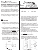
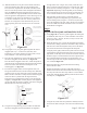

G) With the handleset now in place on the outside of the door,
place the mounting plate (Part #18) and mounting plate
screw (Part #21) in position on the inside of the door, insert
the screw into the top retention boss and tighten until almost
snug. See Figure #11. Insert and tighten the second screw
into the lower boss. Align the handleset on the outside of the
door for appearance and tighten the screws until snug. Do not
overtighten. If your interior set includes a lever see Figure
#11 for lever orientation. Your lever will only rotate in one
direction. It is designed to rotate downward. If your lever
rotates upward, please call customer service at 1-800-522-
7336.
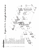
H) Using Figure #1 as your guide, gather together the interior
longplate (Part 19), 1” wood screws (Part #20), clear
alignment jig (provided), Phillips screwdriver, drill, awl (or
nail), and the 4” x 7/64” drill bit (provided).
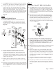
I) Place the clear alignment jig on the inside of the door where
the interior longplate will be installed, see Figure #12.
Place the interior longplate on the door, so that the spindle is
inserted into the star-shaped hub of the latch and the retention
bosses nest in the wide end of the teardrop slots in the
mounting plate, see Figure #11.
J) The interior longplate will be out of alignment when you
first get the retention bosses into the teardrop slots. When the
retention bosses are fully seated, the interior longplate will be
flush to the face of the door. Gently twist the interior longplate
clockwise until it is parallel with the edge of the door,
being sure not to scratch the door when you are twisting the
longplate, see Figure #12. Carefully slip the clear alignment
jig out from under the interior longplate. The interior longplate
should hold itself on the door at this point.
K) Using the clear alignment jig, check to make sure that both
the interior longplate and exterior handleset are aligned to
the edge of the door. Using an awl (or nail), mark the screw
holes on interior longplate and remove it from the door. Drill
the screw holes 3/4” deep, using the 4” x 7/64” bit provided.
Important: Depending on the design that you are installing
there will either be two or four screw holes in each plate. All
screws must be installed to secure the longplate to the door.
L) Following Step 7I and 7J again, re-attach the interior
longplate, using the clear alignment jig to protect the door
from scratching. Then, using the 1” wood screws (Part #20),
secure the longplate to the door snugly, but do not overtighten
the screws. Make sure that the screwdriver does not scratch
the doorknob or longplate.
Step 8
Prepare the Doorjamb and Insta
ll the Strike
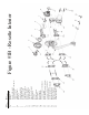
A) Using Figure #1 for reference, gather together the strike plate
for handleset (Part #26), two 1” latch and strike wood screws
(Part #3), a drill, 1” drill bit, the awl (or nail), 4″x7/64” drill
bit, the pencil and chisel.
B) Rotate the knob or lever to retract the latch bolt and carefully
close the door, making sure that the latch bolt is fully retracted
and does not scratch the doorjamb. Slowly release the knob/
lever and let the latch bolt extend against the doorjamb.
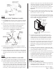
C) Using the pencil, lightly mark the door jamb at the level of the
top and bottom of the latch bolt (Part #14a). These need to be
light marks, so that they can be erased later if needed. Turn the
knob/lever again to retract the latch bolt and re-open the door.
Now extend the marks so that they are approximately 3/4”
from the edge of the door stop trim where the door stops when
it is closed, See Figure #13.
D) Repeat Step 8B, and verify that the latch bolt is falling
between the two marks.
E) Measure the thickness of the door. Take half of the door
thickness and measure that same distance from the edge of the
door stop trim where the door stops when it is closed. Mark
on the door jamb this distance halfway between the two lines
from Step 8C, see Figure #13.
F) Using the awl, mark where the point that is halfway between
the two lines made in Step 8C crosses the line marked in Step
8E.
Figure #12
Figure #13
Page 5 - PK 161
Correct Lever Orientation
(Lever Rotates Downward)
Incorrect Lever Orientation
Door
Edge
Figure #11