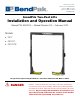
645 Lemonwood Dr. Santa Paula, CA 93060 USA Toll Free: (800) 253-2363 Telephone: (805) 933-9970 bendpak.com GrandPrix Two-Post Lifts Installation and Operation Manual Manual P/N 5900209 — Manual Revision D3 — February 2020 Models: • GP-7 • GP-7LC • GP-7LCS Model GP-7 shown. Designed and engineered by BendPak Inc. in Southern California, USA. Made in China. ⚠ DANGER Read the entire contents of this manual before using this product.
Manual. GrandPrix Series Two-Post Lifts, Installation and Operation Manual, Manual P/N 5900209, Manual Revision D3, released February 2020. Copyright. Copyright © 2020 by BendPak Inc. All rights reserved. You may make copies of this document if you agree that: you will give full attribution to BendPak Inc., you will not make changes to the content, you do not gain any rights to this content, and you will not use the copies for commercial purposes. Trademarks.
Table of Contents Introduction 3 Installation 12 Shipping Information 4 Operation 56 Safety Considerations 4 Maintenance 61 FAQ 6 Troubleshooting 63 Specifications 7 Wiring / Hydraulic Schematic 64 Components 9 Parts Diagrams 65 Labels 78 Installation Checklist 11 Introduction This manual describes the GrandPrix (GP-7 Series) two-post Lifts from BendPak: • • • GP-7. Two-post Lift, 7,000 lb. capacity, 74 inch rise, requires a 13-foot ceiling. GP-7LC. Two-post Lift, 7,000 lb.
Shipping Information Your equipment was carefully checked before shipping. Nevertheless, you should thoroughly inspect the shipment before you sign to acknowledge that you received it. When you sign the bill of lading, it tells the carrier that the items on the invoice were received in good condition. Do not sign the bill of lading until after you have inspected the shipment.
Symbols Following are the symbols used in this manual: ⚠ DANGER Calls attention to a hazard that will result in death or injury. ⚠ WARNING Calls attention to a hazard or unsafe practice that could result in death or injury. ⚠ CAUTION NOTICE Tip Calls attention to a hazard or unsafe practice that could result in personal injury, product damage, or property damage. Calls attention to a situation that could result in product or property damage.
Frequently Asked Questions Question: What kinds of Vehicles can I Lift on my GP-7 Series Lift? Answer: Cars, light trucks, and SUVs; up to 7,000 lbs (3,175 kg) each. Q: How long will it take to raise or lower my Vehicle? A: About 45 seconds, depending on what locking position you use. Q: Does the Lift have to be anchored in place? A: Yes. Two-post Lift posts must be anchored. Your Lift comes with high-quality Anchor Bolts; use only the Anchor Bolts that came with your Lift.
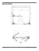
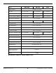
Specifications GrandPrix Two-Post Lifts 7 P/N 5900209 — Rev. D3 — Feb.
Model GP-7LCS Lifting capacity GP-7LC GP-7 7,000 lbs / 3,175 kg A – Rise 54" / 1,372 mm 64" / 1,626 mm 74" / 1,880 mm B – Rise + pad 58" / 1,473 mm 68" / 1,727 mm 78" / 1,981 mm C – Rise + pad + adapter 66" / 1,676 mm 76" / 1,930 mm 86.5" / 2,197 mm D - Minimum pad height E – Height overall 4.5" / 114 mm 106.5" / 2,705 mm 118.5" / 3,010 mm F – Width overall 125" / 3,175 mm G - Outside posts 119.5" / 3,035 mm H – Inside posts 110" / 2,794 mm I - Drive-thru width 89.
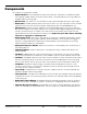
Components GP-7 Series Lift components include: • • • • Powerside Post. The Powerside Post holds the Power Unit, the Safety Lock Release Handle, the Lowering Handle, and the Power Disconnect Switch. The Powerside Post must go under the Cylinder end of the Top Trough. Offside Post. The other Post. The Offside Post goes under the Cables end of the Top Trough. Power Unit. Provides hydraulic power to the Lift. Connects to a 220 VAC power source.
View is from rear of the Lift, looking towards the front. Model GP-7 shown. Not all components shown. GrandPrix Two-Post Lifts 10 P/N 5900209 — Rev. D3 — Feb.
Installation Checklist Following are the steps needed to install a GP-7 Series Lift; perform them in this order. ☐ 1. Review the installation Safety Rules. ☐ 2. Plan for Electrical work. ☐ 3. Make sure you have the necessary Tools. ☐ 4. Select the installation Location. ☐ 5. Check the Clearances. ☐ 6. Review the installation Orientation. ☐ 7. Unload and Unpack the Components. ☐ 8. Install the Post Straps. ☐ 9. Put down Chalk Line Guides for the Posts. ☐ 10. About Embedment. ☐ 11.
Installation The installation process includes multiple steps. Perform them in the order listed. Safety Rules When installing the Lift, your safety depends on proper training and thoughtful operation. ⚠ WARNING Do not install this equipment unless you have automotive Lift installation training. Always use proper Lifting tools, such as a forklift or crane, to raise heavy components. Do not install this equipment without reading and understanding this manual and the safety labels on the unit.
Tools You may need some or all of the following tools: • Rotary hammer drill (or similar) • ¾ inch carbide bit (conforming to ANSI B212.
Clearances GrandPrix Two-Post Lifts 14 P/N 5900209 — Rev. D3 — Feb.
Installation Orientation To determine the front of your Lift, drive a Vehicle in straight (do not back it in) and stop. The front of the Lift is where the front of the Vehicle is. The approach is the direction you drive a Vehicle onto the Lift. Generally the approach is from the rear of the Lift towards the front of the Lift. The orientation of the procedures and drawings in this manual is looking at the Lift from the rear, towards the front, unless specified otherwise.
To identify the Powerside Post and the Offside Post, look at the tops of the Lift Heads in each of the Posts: • • Powerside Post. The Lift Head with widely spaced holes is the Powerside Post. The Powerside Post must go under the Cylinder End of the Top Trough. Offside Post. The Lift Head with the narrowly spaced holes must be the Offside Post. The Offside Post must go under the Cable End of the Top Trough. Important: You must orient the Powerside and Offside Posts this way.
Checking the Safety Spring Before standing up the Posts of the Lift, check to make sure the Safety Spring has not been knocked out of place during transport. The Safety Spring should be in position, as shown below. Post removed for clarity. Not all components shown.
Installing the Post Straps You may want to install the Post Straps on their Posts prior to standing them up. It is not required, but if you install them after standing up the Posts, you will need a ladder to reach them. Important: The Post Strap with the welded plate goes on the Powerside Post. The Post Strap without the welded plate goes on the Offside Post. To install the Post Straps: 1. Bolt the Post Strap with the welded plate to the Powerside Post. 2.
Putting in Chalk Line Guides Based on the specifications for your Lift, create Chalk Line Guides on the ground for the two posts prior to moving them into position. Use the Width Overall value in Specifications for your Lift model to determine where to place the Chalk Line Guides. The Width Overall value is defined as the distance from the back of one base plate to the back of the other base plate. To add Chalk Line Guides: 1. Decide where you want to locate the Lift. 2.
About Embedment Anchor Bolts (also called Wedge Anchors) get their holding strength from how far down into the Hole the Anchor Bolt is installed (called embedment) and how forcefully the Expansion Sleeve presses into the Concrete (based on how much torque is applied). To get enough embedment, you have to understand Effective Embedment, which means the location in the Hole where the Expansion Sleeve presses into the Concrete.
Installing the Posts We strongly recommend having multiple people working together to install the Posts. Concrete specifications are: • • • Depth: 4.25 inches / 108 mm thick, minimum PSI: 3,000 PSI, minimum Cured: 28 days, minimum Anchor Bolt specifications are: • • • • Length: 6.3 inches / 160 mm Diameter: .75 inch / 19 mm Anchor torque: 85 – 95 pound feet (never less than 80 or more than 110) Effective embedment: 3.25 inches / 82.
Go in straight; do not let the drill wobble. Use a carbide bit (conforming to ANSI B212.15-1994). The diameter of the drill bit must be the same as the diameter of the Anchor Bolt. So if you are using a ¾ inch diameter Anchor Bolt, for example, use a ¾ inch diameter drill bit. 5. Vacuum each hole clean. BendPak recommends using a vacuum to get the hole very clean. You can also use a wire brush, hand pump, or compressed air; just make sure to thoroughly clean each hole. Do not ream the hole.
Once past the hole in the Base Plate, the Anchor Bolt eventually stops going down into the hole as the Expansion Sleeve contacts the sides of the hole; this is normal. 7. Hammer or mallet the Anchor Bolt the rest of the way down into the hole. Stop when the Washer is snug against the Base Plate. 8. Plumb each Post; install any needed Shims or the optional Adapter Trays (which let you stack the provided Auxiliary Adapters — also called Extenders — conveniently near the Lift Arms). 9.
About the Lifting Cables ⚠ CAUTION We strongly recommend wearing gloves while handling the Lifting Cables. GP-7 Series Lifts use four Lifting Cables: two Long Cables and two Short Cables. The following drawing shows the two different types of ends on these cables. Note that the ends are exaggerated in this drawing to make it easier to see the two types of ends.
The following drawing is a top view of the components of the Top Trough. Not every component is shown, just the components relevant to installing the Lift. The Offside Post is on the left, the Powerside Post is on the right. Preparing the Top Trough The Top Trough goes between the two posts at the top of the Lift. To prepare the Top Trough, you need to: • • • Route the Lifting cables. Route the safety cables. Connect the hydraulic cables (but not the hydraulic lines).
This drawing is looking down on the Top Trough from above. Tip BendPak recommends installing the two Short Cables (which go on the inner sheaves) first, then proceed to the two longer cables (which go on the outer sheaves). You can do it any way you want, but these instructions go in that order. 3. Put the Button End of first Short Cable into position at the Tie Plate. The following drawing is a side view of how a Short Cable gets routed over the sheaves. 4.
The following drawing is a side view of how the Long Cables get routed over the sheaves on the Offside end of the Top Trough. 7. Once the Button End is in place, route each Long Cable like this: • Under the bottom of the Cylinder side sheave and then over the top of it. • Over the top of the Offside end sheave and then under the bottom of it. • Past the Cylinder side sheave (without touching it), towards the two-groove sheave on the Powerside end.
8. Secure the cables with the top of the Tie Plate using a flat head and hex head bolts. The following drawing shows how the Button ends and cables should appear just after you secure the top of the Tie Plate into position. Important: Make sure the cables are carefully aligned in their sheaves; you want to avoid as much contact as possible between the cable and the sheaves while the Lift is in motion. This makes the Lift move more smoothly and extends the life of the cables and the sheaves. 9.
To route the Safety Cable: 1. Locate the Safety Cable. The Safety Cable is a long, thin steel cable with a loop on one end; the other end does not have a loop. The loop end of the Safety Cable connects to the safety mechanism on the Offside Post; the ends are not interchangeable. Make sure to orient the Safety Cable so that the loop end stays on the Offside Post side of the Lift. 2.
Connecting the Hydraulic Cables The Hydraulic Cables connect to ports on the Hydraulic Cylinder on one end and to the Hydraulic Lines on the other end. Together, the Hydraulic Cables and Hydraulic Lines move hydraulic power to and from the Hydraulic Cylinder. The two Hydraulic Cables are: • • Long Hydraulic Cable. Connects to the Hydraulic In port. Short Hydraulic Cable. Connects to the Hydraulic Return port. To connect the Hydraulic Cables: 1.
Installing the Top Trough The Top Trough holds the Hydraulic Cylinder and the Lifting Cables. It also supports the Trip Stop Tube underneath it. ⚠ CAUTION Important: Watch out for the already-installed cabling. Make sure they do not get in the way as you move the Top Trough into position. The Top Trough must be installed in a specific orientation: the end with the Hydraulic Cylinder must go over the Powerside Post; the end with the sheave assemblies must go over the Offside Post.
Installing the Power Unit The standard Power Unit for your Lift is 208-240 VAC, 50/60 Hz, 1 phase. Note that the motor is not thermally protected. The Power Unit must be installed on the Powerside Post. Important: Do not connect the Power Unit to the Hydraulic System or power at this time. To install the Power Unit: 1. If the Lift Head (also called the carriage) is blocking access on the inside of the Powerside Post to the holes used to attach the Power Unit, raise it out of the way.
Installing the Safety Assemblies and the Safety Cable Each GP-7 Lift has two Safety Assemblies: one on the Powerside Post (above the Power Unit) and the other on the Offside Post. The two Safety Assemblies work together to take the load off the Hydraulic Cylinder and the Lifting cables once the Lift has reached the desired working height. The Safety Assemblies need to be disengaged at the same time so that the Lift Arms lower together.
To install the two Safety Assemblies: 1. For the Powerside Post, locate the Safety Assembly with the Safety Lock Release Handle, a safety clevis pin, two springs, and one cotter pin (sometimes called a hairpin). 2. Put one of the springs next to the head of the safety clevis pin, then insert the safety clevis pin, from the left, through the hole in the left welded plate, then through the Safety Assembly, and then through the right welded plate. 3.
The Safety Cable connects the two Safety Assemblies together. Note: The Safety Cable should have been installed earlier. The following procedure describes how to hook up the Safety Cable on the Offside Post and on the Powerside Post. To connect the Safety Cable: 1. On the Offside Post, bring the loop end of the Safety Cable down through the inside of the Offside Post. 2.
7. Pull the straight end of the Safety Cable out to the front of the Powerside Post underneath the Safety Sheave; make sure the Safety Cable is seated correctly in the Safety Sheave. 8. Put the straight end of the Safety Cable over the front of the Welded Pin and into the hole in the Welded Pin with Threads, between the two nuts. 9. Pull any slack out of the Safety Cable, then tighten the nuts.
Installing the Trip Stop Tube The Trip Stop Tube is installed on the underside of the Top Trough. The Trip-Stop Tube stops upward movement of the Lift; if you are raising a Vehicle and it hits the TripStop Tube, the Lift immediately stops moving up. To install the Trip Stop Tube: 1. On the Powerside, slide the Trip Stop Tube through the welded Post Strap, then fasten the threaded end of the Microswitch Cable through the hole in the tube. 2.
Installing the Microswitch and the Microswitch Cable The Microswitch is the mechanism by which the Trip Stop Tube stops the Lift, if necessary. To install the Microswitch Cable and the Microswitch: 1. Install the Microswitch Assembly on the right side of the Powerside Safety Assembly using two button head screws. 2. Find the loop end of the Microswitch Cable on the inside of the Powerside Post, then push it through to the outside of the Powerside Post just under the Microswitch Sheave. 3.
About Fluid Contamination IMPORTANT! PLEASE READ NOW Hydraulic Fluid Contamination poses a serious issue for your Lift; contaminants such as water, dirt, thread seal tape, and other debris can get into the Hydraulic Hoses and Fittings on the Lift, making your new Lift inoperable. Your Lift is shipped with clean components; however, BendPak strongly recommends that you take secondary precautions and clean all Hydraulic Hoses and Fittings prior to making connections.
Installing Hydraulic Lines The two metal Hydraulic Lines run along the outside of the Powerside Post. They connect to ports on the Power Unit on one end and to the flexible Hydraulic Hoses (in the Top Trough) on the other end. The two flexible Hydraulic Hoses were connected to the Hydraulic Cylinder earlier in the installation. Note: The two metal Hydraulic Lines look similar, but they are not the same. Make sure you orient them correctly.
2. Remove the plastic plugs from the appropriate ports on the Power Unit: the Hydraulic Return port (left rear connector) and the Hydraulic Power Out port (right front connector). 3. For the Hydraulic Return port, install a 90° hydraulic fitting. Connect that 90° fitting to the fitting on the bottom of the Hydraulic Return Line. 4. For the Hydraulic Power Out port, connect a 90° ORB fitting. Connect that 90° ORB fitting to the fitting on the bottom of the Hydraulic Power Line.
Connecting the Lifting Cables The threaded ends of the Lifting Cables, which were installed in the Top Trough earlier in the installation, connect to the Lift Heads inside the Offside and Powerside Posts; two Lifting Cables per Post. To connect the Lifting Cables: 1. Inside the Powerside Post, insert the threaded ends of the two Lifting Cables through the holes adjacent to the Retainer on the top of the Lift Heads.
3. For the Offside Post, repeat the same process, except the holes adjacent to the Retainer on the top of the Lift Heads are narrowly spaced, compared to the holes on the Powerside Post. 4. Place one M18 washer and M18 Nyloc nut on the threaded cable end; tighten the nuts until taut, making sure both cables have equal tension. GrandPrix Two-Post Lifts 43 P/N 5900209 — Rev. D3 — Feb.
Installing the Safety Covers There are two Safety Covers, one for each Safety Assembly. Refer to Installing the Safety Assemblies and the Safety Cable for more information about Safety Assemblies. The Safety Covers are not interchangeable: • • The Offside Post Safety Cover can be installed in either orientation. The Powerside Post Safety Cover can only be installed in one orientation: there is a slot on the front for the Safety Lock Release Handle and a hole in the bottom for the Microswitch Cable.
Make sure an Angled Arm Spacer is in place on top of each Angled Lift Arm; they are not necessary for Straight Lift Arms. 4. Repeat Steps 2 and 3 for each of the other Lift Arms. ⚠ DANGER The gears must be positioned and adjusted properly. Confirm proper gear engagement prior to operation of the Lift. Periodic inspection and adjustment is also required. Failure to properly inspect and adjust the arm restraint gears on all four arms can result in damage to the Vehicle, injury, or even death. 5.
6. Tighten the Gear Ring bolts. 7. Verify the operation of the Arm restraints by pulling up on the Key Ring of the Arm Restraint Pin. Pivot the arms back and forth and test the operation of the Arm Restraint Pin in various positions. Make sure the Lift Arms do not move when a force of approximately 100 pounds or less is applied laterally to the fully extended arms. 8.
Contact the Electrician As mentioned previously, there are certain installation tasks that require a certified Electrician. ⚠ DANGER All wiring must be performed by a licensed, certified Electrician. If someone who is not a certified Electrician attempts these tasks, they could damage the Lift or be electrocuted, resulting in serious injury or even death. The Electrician needs to: • • • • Attach a Power Cable with an appropriate plug.
Connect and Prepare the Power Unit There are several things you need to do to get your Power Unit ready for normal operation: • • • • • Attach the Power Unit to the Powerside Post. Should already be done, described in Installing the Power Unit. Attach the Hydraulic Line and the Return Line to the correct locations on the Power Unit. Should already be done, described in Installing Hydraulic Lines. Attach the Power Unit to a power source. Covered in this section. Wire the Microswitch.
3. Wire the Microswitch to the incoming power source per the following drawing. GrandPrix Two-Post Lifts 49 P/N 5900209 — Rev. D3 — Feb.
Add Hydraulic Fluid The Hydraulic Fluid Reservoir on the Power Unit must be filled with Hydraulic Fluid or automatic transmission fluid before you begin normal operation of the Lift. When you receive the Lift, the fluid reservoir is empty. The Hydraulic Fluid Reservoir holds approximately ~3.7 gallons / ~14 liters. The Power Unit will not work correctly until the reservoir is filled with approved Hydraulic Fluid.
Installing a Power Disconnect Switch ⚠ WARNING A Power Disconnect Switch is not provided with this equipment. A Power Disconnect Switch is a National Electrical Code (NEC) requirement. They are designed to interrupt main electrical power in the event of an electrical circuit fault, emergency situation, or when equipment is undergoing service or maintenance. Make sure to install a Power Disconnect Switch that is properly rated for the incoming power source.
Final Leveling Before operating your Lift, you need to make sure that both the Lift posts and the Lift arms are level: • Lift Posts: The Posts must be the same distance apart at the top and at the bottom. To make sure the Posts are level, measure the distance between the two Posts six inches below the Top Trough and one foot off the ground (you will need to move the Lift Arms out of the way). The two measurements (A and B in the drawing below) must be the same.
Lubricating BendPak recommends lubricating the following locations on the Lift before starting normal operation and on a monthly basis afterwards, to keep your Lift working better and longer: • • The four inside corners of both Posts (which is where the Slide Blocks slide) The pins of the Microswitch Sheave and the Safety Sheaves We recommend using white lithium grease or light axle grease as the lubricant.
Perform an Operational Test Before putting your Lift into normal operation, we recommend raising and lowering it several times with a typical Vehicle on the Lift. This will help you get a feel for how to operate the controls and help get any residual air out of the Hydraulic System (sometimes called “bleeding” the system). ⚠ DANGER Automotive Lifts are dangerous tools when used by inexperienced, impaired, or distracted technicians.
8. Wait for one minute. NOTICE The Power Unit is not a constant duty motor; it cannot be run continuously. 9. Repeat the process, this time raising the Lift, engaging it on a Safety Lock position, taking it off the Safety Lock position, and then lowering it back down to the ground. Again, follow the instructions in Raising the Lift and Lowering the Lift to safely raise and lower a Vehicle on the Lift, including engaging it on its Safety Locks. 10.
Operation This section describes how to operate your Lift. ⚠ DANGER Automotive Lifts are dangerous when used by inexperienced, impaired, or distracted operators. When you even hear the words “automotive lift,” your brain should automatically register the fact that lifting a Vehicle is a serious endeavor with life-threatening risks, especially if mandatory lifting precautions are ignored.
Raising the Lift This section describes how to raise a Vehicle on the Lift. ⚠ WARNING: Never raise a Vehicle whose weight exceeds the rated capacity of the Lift. Do not leave the controls until the Lift is engaged on its Safety Locks. To raise a Vehicle: 1. Make sure the Lift Arms are on the ground in their full drive-thru position. 2. Drive the Vehicle in. ⚠ CAUTION When driving a Vehicle in, keep to the middle of the area between the Posts.
8. Check all four Lift Arms again to make sure the Lift Pads are directly under the Lifting Points. If they are not, adjust them so that they are. If necessary, move the Lift all the way back down to the ground and start over. 9. Push the Up Pushbutton to raise the Vehicle until it is a few inches off the ground. 10. Release the Up Pushbutton, then check to make sure the Lift Pads have solid contact with the Vehicle’s Lifting Points and that the Vehicle is balanced on all four of the Lift Arms.
Lowering the Lift To lower the Lift, you first raise it a small amount to get it off the Safety Lock, then bring it down. To lower the Lift: 1. Check under and around the Vehicle to make sure the area is clear of all obstructions. If you find any, move them out of the way. 2. Press and hold the Up Pushbutton for a few seconds to move the Lift off its Safety Locks. Raise the Lift at least two inches to get clear of the Safety Locks. 3.
About Safety Locks Your Lift has 11 Safety Lock positions, spaced every four inches; having multiple Safety Lock positions lets you lock the Lift at the best height for what you want to do. A Safety Lock position is when the Lift is engaged on both of the Lift’s Safety Locks at the same height on both Posts. Important: Always make sure both Safety Locks are engaged at the same height on both Posts.
Maintenance ⚠ DANGER Before performing any maintenance on your Lift, make sure it is completely disconnected from power. The Lift uses electrical energy; if your organization has Lockout/Tagout policies, make sure to implement them before performing any maintenance. If you come into contact with high voltage/current, you could be injured or killed. To maintain your Lift: • • Daily: Keep the Lift clean. Wipe up any spills, clean any dirt.
Wire Rope Inspection and Maintenance Your Lift’s Lifting Cables are made of Wire Rope, which means they are strands of steel twisted into a helix with a diameter greater than 3/8 inch / 9.52 mm. Your Lift’s Wire Rope should be inspected regularly: • Lifting Cables should be replaced when there are visible signs of damage or extreme wear. Do • Lifting Cables should be maintained in a well-lubricated condition at all times. not use the Lift if it has damaged or worn Lifting Cables.
Troubleshooting Issue Action to Take Lift does not raise or does not lower, Make sure there is sufficient Hydraulic Fluid in the reservoir. once raised. Make sure there is no air in the Hydraulic System. Make sure none of the Hydraulic Lines are pinched or leaking. Make sure the Power Unit is getting power. If the Hydraulic Fluid is dirty, replace it with clean fluid. Make sure the Lift is not overloaded. Make sure the load on the Lift is balanced. Arms move erratically or squeaks when in use.
Wiring and Hydraulic Schematic GrandPrix Two-Post Lifts 64 P/N 5900209 — Rev. D3 — Feb.
Parts Diagrams GrandPrix Two-Post Lifts 65 P/N 5900209 — Rev. D3 — Feb.
GrandPrix Two-Post Lifts 66 P/N 5900209 — Rev. D3 — Feb.
GrandPrix Two-Post Lifts 67 P/N 5900209 — Rev. D3 — Feb.
GrandPrix Two-Post Lifts 68 P/N 5900209 — Rev. D3 — Feb.
GrandPrix Two-Post Lifts 69 P/N 5900209 — Rev. D3 — Feb.
GrandPrix Two-Post Lifts 70 P/N 5900209 — Rev. D3 — Feb.
GrandPrix Two-Post Lifts 71 P/N 5900209 — Rev. D3 — Feb.
GrandPrix Two-Post Lifts 72 P/N 5900209 — Rev. D3 — Feb.
GrandPrix Two-Post Lifts 73 P/N 5900209 — Rev. D3 — Feb.
GrandPrix Two-Post Lifts 74 P/N 5900209 — Rev. D3 — Feb.
GrandPrix Two-Post Lifts 75 P/N 5900209 — Rev. D3 — Feb.
GrandPrix Two-Post Lifts 76 P/N 5900209 — Rev. D3 — Feb.
GrandPrix Two-Post Lifts 77 P/N 5900209 — Rev. D3 — Feb.
Labels GrandPrix Two-Post Lifts 78 P/N 5900209 — Rev. D3 — Feb.
GrandPrix Two-Post Lifts 79 P/N 5900209 — Rev. D3 — Feb.
GrandPrix Two-Post Lifts 80 P/N 5900209 — Rev. D3 — Feb.
GrandPrix Two-Post Lifts 81 P/N 5900209 — Rev. D3 — Feb.
Maintenance Log GrandPrix Two-Post Lifts 82 P/N 5900209 — Rev. D3 — Feb.
Maintenance Log GrandPrix Two-Post Lifts 83 P/N 5900209 — Rev. D3 — Feb.
1645 Lemonwood Drive Santa Paula, CA 93060 USA © 2020 by BendPak Inc. All rights reserved. bendpak.