
Full Product Manual

GrandPrix Two-Post Lifts 9 P/N 5900209 — Rev. D3 — Feb. 2020
Components
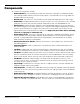
GP-7 Series Lift components include:
• Powerside Post. The Powerside Post holds the Power Unit, the Safety Lock Release Handle,
the Lowering Handle, and the Power Disconnect Switch. The Powerside Post must go under the
Cylinder end of the Top Trough.
• Offside Post. The other Post. The Offside Post goes under the Cables end of the Top Trough.
• Power Unit. Provides hydraulic power to the Lift. Connects to a 220 VAC power source. Includes
the button that raises the Lift and an Hydraulic Fluid reservoir that must be filled before use.
• Safety Locks. Hold the Lift Arms while they are raised. Multiple Safety Locks let you select the
best Lift Arm height for your needs. Safety Locks use gravity and intelligent engineering to hold the
Lift Arms up once they are on a Safety Lock; even if the Lift loses power, the Lift Arms will stay
right where they are if they were left on a Safety Lock.
Only leave your GP-7 Series Lift fully
lowered or engaged on a Safety Lock.
• Slack Safety Locks. The Lift has a backup set of safety locks called the Slack Safeties. During
normal operation, the Lifting Cables hold back the Slack Safeties so that they do not engage. If,
however, a Lifting Cable were to break (which rarely happens!), the Slack Safety for the Lifting
Cable that broke would kick in immediately.
• Safety Lock Release Handle. Releases the Lift from its current Safety Lock. Used as part of
the lowering process.
• Lowering Handle. Lowers a Vehicle from a raised position when used with the Safety Lock
Release Handle.
• Lift Pads. Rubber pads that contact the Lifting Points of the Vehicles you raise. Also included
with your Lift are three sets of extensions (short, medium, tall) that can be used with the Lift Pads.
• Lift Arms. Extendable steel arms that attach to the Lift Heads. Lift Arms hold the Lift Pads; after a
Vehicle is moved into place, the Lift Arms are moved so that the rubber pads contact the Lifting
points on the Vehicle. The Lift Arms are one of the components that actually holds a Vehicle up.
• Lift Heads. Sometimes called carriages. Lift Heads move up and down in the Posts. They
connect to the Lift Arms, so when the Lift Heads move up, the Lift Arms (and anything on them)
also move up, thus raising the Vehicle.
• Top Trough. The beam across the top of the Lift; it supports the Lift’s structure and holds the
Hydraulic Cylinder and the Lifting Cables.
• Trip Stop Tube. Located on the underside of the Top Trough, the Trip Stop Tube stops upward
movement of the Lift. If you are raising a Vehicle and it hits the Trip Stop Tube, the Lift immediately
stops moving up.
• Power Disconnect Switch. Immediately interrupts main electrical power to the Lift. Used for
electrical circuit faults, emergency situations, or when Lift is undergoing service or maintenance.
• Thermal Disconnect Switch. Overload device that makes sure the equipment shuts down if
there is an overload or an overheated motor. The Lift’s motor has no thermal overload protection.