VoIPMaster™ Version 4.
MasterVoIP VoIP to GSM Gateway Usage Warnings 1) High voltage transients, surges, and other power irregularities can cause extensive damage. It is the user's responsibility to provide a power protection system. 2) It is the user's responsibility to install, operate, and maintain the system in accordance with all applicable codes, regulations, and safety measures. Trademark and Patents All trademarks, patents and copyrights apply.
Februaray-2006 Page 3 / 42 MasterVoIP VoIP to GSM Gateway Dear Customer, We thank you for purchasing our VoIP Master VoIP to GSM Gateway. The information in this manual does not constitute a warranty of performance, although the information has been compiled and checked for accuracy by Eurotech Communication Ltd. All our products are developed and produced by experienced engineers, who aspire to achieve customer satisfaction, utility value and reliability of products.
TABLE OF CONTENTS 1 2 3 3.1 Getting Started................................................................................................................................................. 5 Check your package Items............................................................................................................................... 7 VoIP Client ATA ...............................................................................................................................................
1 Getting Started Eurotech Communication team is glad you have chosen to use the Eurotech’s VoIPMaster GSM to VoIP gateway for greatly saving your call costs. We will do our best to make your installation efforts as well as day-to-day configuration and monitoring tasks be pleasant tasks as possible. We wish you a smooth operation while greatly saving your office mobile phone calls.
MasterVoIP VoIP to GSM Gateway Completing this you shall start the installation procedure of the VoIPMaster following the Set-up and Installation as follows: Installing the Manager Application Define the Com port Connection – to enable a PC to VoIP master proper connection Port and SIM Settings – to associate and set SIM and Ports accordingly Dial Settings for the GSM Port – to define policies and profile of behaviour when dialling SIM Settings – regarding with usage limits and other optional mode
2 Check your package Items Please verify your package contains the following components (some were ordered specific) before installation: Main Hardware Device – The VoIP Master Gateway 110/220V Electric Power converter to 24V with cables supplied VoIP master software Installation CD - Installation kit for MS-Windows Management Application, this User Manual file and additional auxiliary utilities.
3 VoIP Client ATA Before using this device please perform the following actions: 1. Connect the VoIPMaster (Which include the VoIP Client ATA as a built-in module) to the IP network via the RJ-45 connection near the 2 LEDs and power supply side. You must have an account with a VoIP termination service provider or you should register an extension with a SIP Gateway/Server. Get all needed data from your provider (such as: user name, Password, server IP addresses ports etc.). 2.
3.1.
3.1.3 3.1.3.1 Basic Operations Getting Familiar with the Key Pad and the Voice Prompt VoIP Client ATA has a stored voice prompt menu for quick browsing and simple configuration. To enter this voice prompt menu, simple pick up the phone and press the button on the VoIP Client ATA; or pick up the phone and dial “***”. The following table shows how to use the voice prompt menu to configure the device for required voice prompts.
3.1.4 Placing Phone Calls 3.1.4.1 Calling phone or extension numbers There are currently two methods to make an extension number call: 1. Dial the extension number directly and wait for 4 seconds. (Default “No Key Entry Timeout”). Or: 2. Dial the number directly, and press # (assuming that “Use # as dial key” is selected in the web configuration). Other functions available during the call are call-waiting/flash, call-transfer, and call-forwarding supplementary call services. 3.1.4.
3.1.4.3 Blind Transfer Assuming that call party A and B are in conversation. A wants to Blind Transfer B to C: 1. A presses FLASH (on the analog phone, or Hook Flash for old model phones) to get a dial tone. 2. Then “A” dials *87 then dials C’s number, and then # (or waits for 4 seconds) 3. “A” can hang up. Note: Call Feature has to be set to YES.
3.1.5 Call Features 3.1.6 Fax Support The Following table shows the call features of VoIP Client ATA. Key Call Features *30 Block Caller ID (for all subsequent calls) *31 Send Caller ID (for all subsequent calls) *67 Block Caller ID (per call) *82 Send Caller ID (per call) *50 Disable Call Waiting (for all subsequent calls) *51 Enable Call Waiting (for all subsequent calls) *70 Disable Call Waiting. (Per Call) *71 Enable Call Waiting (Per Call) Unconditional Call Forward.
3.1.7 LED Light Pattern Indication Following are the LED light pattern indications.
3.2 Configuration Guide 3.2.1 Configuring VOIP Client with a Web Browser 3.2.1.1 Access the Web Configuration Menu 3.2.1.2 End User Configuration VoIP Client ATA has an embedded Web server that will respond to HTTP GET/POST requests. VoIP Client ATA is enabled with embedded HTML pages, which allow a user to configure the IP phone, through a Web browser, such as Microsoft’s IE and AOL’s Netscape. First, get the IP address of the VOIP Client through section 2.1 with menu option 02.
The following table describes the various configurations to be performed: End User Password This contains the password to access the Web Configuration Menu. This field is case sensitive with max.
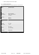
Here are the status details shown: Februaray-2006 Page 17 / 42 MasterVoIP VoIP to GSM Gateway
MAC Address The device ID, in HEX format. This is very important ID for ISP troubleshooting. WAN IP Address This field shows WAN port IP address. Product Model This field contains the product model info. Software Version System Uptime Registered PPPoE Link Up NAT NAT Mapped IP NAT Mapped Port Statistical Status Februaray-2006 Program: This is the main software release. This number is always used for firmware upgrade. Bootloader: This is normally not changed.
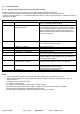
3.2.1.3 Advanced User Configuration To login to the Advanced User Configuration page, follow the instruction in section 3.2.1, they will lead You to the following page: (The password is case sensitive with a maximum length of 25 characters and the factory default password for Advanced User is “admin”).
The following window if for advanced configuration regarding IP, SIP, QoS, NAT, IP Telephony modes setting: Februaray-2006 Page 20 / 42 MasterVoIP VoIP to GSM Gateway
Admin Password Administrator password: Only the administrator can configure the “Advanced Settings” page. Password field is purposely left blank for security reasons after Pressing update and save. The maximum password length is 25 characters. SIP Server This field contains the URI string or the IP address (and port, if different from 5060) of the SIP proxy server. e.g., the following are some valid examples: sip.my-voip-provider.com, or sip:my-company-sip-server.com, or 192.168.1.
Februaray-2006 Page 22 / 42 MasterVoIP VoIP to GSM Gateway
SIP User ID This field contains the user part of the SIP address for this phone. e.g., if the SIP address is: sip:my_user_id@my_provider.com, then the SIP User ID is: my_user_id. Please do NOT include the preceding “sip:” scheme or the host portion of the SIP address in this field. SIP User ID User account information, provided by VoIP service provider (ITSP), usually has the digit form of a phone number (or is actually a phone number).
Voice Frames per TX This field contains the number of voice frames to be transmitted in a single packet. When setting this value, the user should be aware of the requested packet time (used in SDP message) as a result of configuring this parameter. This parameter is associated with the first vocoder in the above vocoder Preference List or the actual used payload type negotiated between the 2 conversation parties at run time. e.g.
Dial Plan Prefix No Key Entry Timeout Use # as Send Key Local SIP port Local RTP port Use Random Port keep-alive interval Use NAT IP Proxy-Require NAT Traversal Firmware Upgrade Februaray-2006 This value contains the dial plan prefix string (typically an ASCII numeric string). If it is not blank, then this string will be used as a prefix to the target URI string in the “To” header field of an INVITE message. Default is 4 seconds.
Via TFTP Server Via HTTP Server Automatic HTTP Upgrade SUBSCRIBE for MWI Offhook Auto-Dial Enable Call Feature Disable Call Waiting Send DTMF DTMF Payload Type Februaray-2006 This is the IP address of the configured tftp server. If it is non-zero or not blank, the IP phone will attempt to retrieve new configuration file or new code image (update) from the specified tftp server at boot time.
Send Flash Event This parameter allows the user to control whether to send an SIP NOTIFY message indicating the Flash event, or just to switch to the voice channel when the user presses the Flash key. FXS Impedance Selects the impedance of the analog telephone connected to the Phone port. Select the Caller ID Scheme to suit the standard of different area.
Syslog Level Select the ATA to report the log level. Default is NONE. The level is one of DEBUG, INFO, WARNING or ERROR.
3.2.1.4 Saving the Configuration Changes Once a change is made, the user should press the “Update” button in the Configuration Menu. The IP phone will then display the following screen to confirm that the changes have been saved. Users are recommended to power cycle the VOIP Client-488 after seeing the above message. 3.2.1.5 Remotely rebooting VoIP Client ATA The administrator of the phone can remotely reboot the phone by pressing the “Reboot” button, at the Configurations menu button.
3.3 Restoring the Factory Default Settings Warning !!! Restoring the Factory Default Settings will DELETE all configuration information of the device. Please backup or print out all the settings before attempting the following steps. Please disconnect the network cable and power cycle the unit, before trying to reset the unit to the factory defaults. The steps are as follows: Step 1: Find the MAC Address of the device. The MAC address of the device is located at the bottom of the device.
3.4 VoIP Master 3.4.1 What is the VoIP Master and how it works This device connects GSM cellular telephones to the internet, by way of VoIP (Voice over Internet Protocol). A GSM module, including a SIM card, is installed inside the VoIP device. A SIM card is a smart card that is received with a subscription to a cellular telephone network.
1. From your cellular phone, you can dial to the VoIP device. 2. The GSM module in the VoIP device provides you with a dial tone of Voice over Internet Protocol. 3. You can now dial and make a telephone connection by way of the internet which has near 0 cost. Main usage features: • Up to 32 cellular phones can use the VoIP device for connection to the internet in parallel. • A local desktop telephone can be connected to the VoIP device.
3.4.2 Set-up and Installation Insert SIM and connect the cables as described below. 1. Insert SIM card into the VoIP Master as follows: a. Using the tip of the antenna (or a similar object), press on the small yellow button on the left side of the gateway, as pictured below. A SIM drawer pops out. b. Insert the SIM into the drawer as pictured below. Ensure that the angled notch of the SIM is in the matching corner of the SIM drawer (upper left corner). Ensure that the SIM is flat in the drawer. c.
Februaray-2006 Page 34 / 42 MasterVoIP VoIP to GSM Gateway
3.4.3 Installing the Manager Application Before operation, configuration settings must be made in the VoIP Master gateway. Configuration is done by a manger application in the computer. Install the manager application on the software cd, then define the comport connection, as described in this chapter. 1. Insert the VoIP Master CD into the computer drive. 2. In Windows Explorer, navigate to Icon (in the software disk). 3. Double click the Icon, wait till the installation window will open.
4. Click Next. The Setup Type window opens. 5. Select “Complete” and click “Next”. The “Begin Installation” window opens. VoIP Master 6. Click Install. Wait till the VoIP Master Manager application will install itself. 3.4.4 Define the Com port Connection After installing the manager application, launch it and define the Comport to which the VoIP Master is connected. 1.
Start > Programs > EuroTech Communications > VoIP Master Manager. The VoIP Master Manager window opens. VoIP Master 2. In the toolbar, press . The Select Connection window opens. 3. Select the Com Port in the computer to which the VoIP The connection indicators in the lower right corner of the window blink green: Master is After installing the Manager and defining the port connection, define port and SIM Settings as described in the following chapter.
Februaray-2006 Page 38 / 42 MasterVoIP VoIP to GSM Gateway
3.4.5 Port and SIM Settings This chapter details port to SIM association as well as required and optional settings. 3.4.5.1 Dial Settings for the GSM Port After defining the Comport, press GSM Port in the left pane. The Port Setting window is displayed. Define dial settings in this window as follows: 1. In the Dial pause box, set the time interval, whereupon a dialed number is dispatched after the designated delay time. Each unit is 0.1 second.
3.4.5.2 SIM Settings After making the port settings, press a SIM icon in the left pane. The SIM Setting window opens. VoIP Master 1. In the PIN Code box, enter the PIN number of the SIM. 2. In the Network box, enter the GSM network number of the SIM. 3. In boxes 1 through 8, set enter telephone number prefixes to which this SIM can dial. 4. Press Write Settings.
3.4.5.3 Follow Me Settings If there is no answer on the local phone connected to your VoIP gateway you can use a “Follow me” feature. The “Follow me” feature connects the incoming call to your cellular phone. To activate, after making SIM settings, press Follow me in the left pane. The Follow Me Setting window opens. VoIP Master 1. Set the Mode box to ON. 2. In the Rings Number box, enter the number of times the local phone will ring before being diverted to the "Follow me" function. 3.
3.4.5.4 Call Back Settings A call back feature is available with the VoIP master gateway. If person A is having a conversion via the VoIP master gateway, and person B attempts to make a phone call via the same VoIP: 1. Person B will receive a busy signal. 2.