
User's Manual
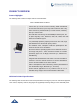
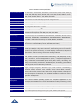

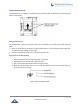
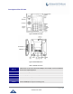
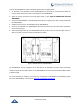
Table Of Contents
- DOCUMENT PURPOSE
- CHANGE LOG
- Firmware Version 1.0.3.180
- Firmware Version 1.0.3.177
- Firmware Version 1.0.3.171
- Firmware Version 1.0.3.162
- Firmware Version 1.0.3.158
- Firmware Version 1.0.3.144
- Firmware Version 1.0.3.131
- Firmware Version 1.0.3.92
- Firmware Version 1.0.3.75
- Firmware Version 1.0.3.62
- Firmware Version 1.0.3.55
- Firmware Version 1.0.3.46
- Firmware Version 1.0.3.37
- Firmware Version 1.0.3.30
- Firmware Version 1.0.3.22
- Firmware Version 1.0.3.6
- Firmware Version 1.0.1.54
- Firmware Version 1.0.1.39
- Firmware Version 1.0.1.29
- WELCOME
- PRODUCT OVERVIEW
- GETTING STARTED
- GETTING TO KNOW GXV3240
- MAKE PHONE CALLS
- Register SIP Accounts
- Dial a Number Directly
- Redial
- Dial a Number via Contacts
- Dial a Number via Call History
- Direct IP Call
- Answer a Call
- Call Hold
- Call Recording
- Mute
- Turn on Video during Audio Call
- Call Details during Call
- Switch Audio Channel during Call
- Call Transfer
- 6-Way Conference
- Missed Call
- DND (Do Not Disturb)
- Voicemail/Message Waiting Indication
- Call Forward
- Multi-Purpose Keys
- Shared Call Appearance (SCA)
- Call Features
- CONTACTS
- LDAP PHONEBOOK
- BROADWORKS XSI CONTACTS
- BLACKLIST
- CALL HISTORY
- SMS
- CALENDAR
- GS MARKET
- TOOLS
- FTP SERVER
- RECORDER
- CAMERA
- CONNECTING GXV3240 TO GDS3710 DOOR SYSTEM
- MULTIMEDIA
- BROSWER
- RSS NEWS
- BS-IM&P
- ACTIONURL
- PNP
- CONNECT TO NETWORK AND DEVICES
- EXPERIENCING THE GXV3240 APPLICATION PHONE

P a g e | 27
GXV3240 User Guide
LAN Port
10/100/1000Mbps RJ-45 port connecting to Ethernet.
Power Jack
12V DC Power connector port.
EXT Port
RJ11 connector port to connect the extension board GXP2200EXT.
Connecting the GXV3240
To setup your GXV3240, please follow the steps below:
1. Connect the handset and main phone case with the phone cord;
2. Connect the LAN port of the phone to the RJ-45 socket of a hub/switch or a router (LAN side of the
router) using the Ethernet cable;
3. Connect the 12V DC output plug to the power jack on the phone; plug the power adapter into an
electrical outlet. If PoE switch is used in step 2, this step could be skipped;
4. The LCD will display booting up or firmware upgrading information. Before continuing, please wait
for the main screen display to show up;
5. Using the web configuration interface or from the menu of the touch screen, you can further
configure network connection using static IP, DHCP and etc.
GXV3240 Extension Module (GXP2200EXT)
The GXV3240 uses GXP2200EXT as the extension module. The extension module is an ideal solution for
the busy enterprise environment looking to add the ability to receive and dispatch calls efficiently. Each
GXP2200EXT extension module has 20 programmable buttons, LEFT and RIGHT buttons, supporting 40
Multiple Purpose Keys to be configured. GXV3240 supports up to 4 extension modules, adding 160 fully
programmable phone extensions to the phone.
Table 5: GXP2200EXT Packaging
GXP2200EXT Board
1
GXP2200EXT Stand
1
RJ11-RJ11 Cable
1
Connector Plate
1
Screws
4
Quick Installation Guide
1
Note:
The GXP2200EXT is an additional accessory for the GXV3240. Therefore, the GXP2200EXT (including
extension module accessories for installation) is not included in the GXV3240 box.