
User's Manual

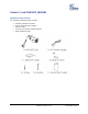

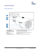
Table Of Contents
- Welcome
- Connect your GXV3672_HD/FHD
- Product Overview
- Installation Guide
- Basic Settings Explanation
- System Settings Page
- Figure 3: System Settings Page
- Video & Audio Setting Page
- Figure 4-1: Video & Audio Settings Page
- Figure 4-2: Video & Audio Settings Page
- CMOS Settings Page
- Figure 5: CMOS Settings Page
- Networking Setting Page
- Figure 6: Networking Setting Page
- DDNS Settings Page
- Figure 7: DDNS Setting Page
- SIP Setting Page
- Figure 8-1: SIP Setting Page
- Figure 8-2: SIP Setting Page
- Status Page
- Figure 9: Status Page
- Advanced Settings Explanation
- User Management Page
- Figure 10: User Management Page
- Maintenance Page
- Figure 11: Maintenance Page
- SMTP Setting Page (Email Alarm)
- Figure 12: SMTP Setting Page
- FTP Settings Page (Upload Alarm)
- Figure 13: FTP Setting Page
- Alarm Server Settings Page (Upload Alarm to supported VMS or HTTP Server)
- Figure 14: Alarm HTTP Server Setting Page
- Motion Detection Configuration Page (Set Alarm)
- Figure 15-1: Motion Detection Configuration Page
- Figure 15-2: Motion Detection Schedule Configuration Page
- Syslog Settings Page (Troubleshooting)
- Figure 16: Alarm Server Setting Page
- Software Upgrade
- Software Upgrade via TTFP, HTTP or HTTPS
- Figure 17: Firmware Upgrade and Provisioning
- Instructions for local firmware upgrade using TFTP server:
- Configuration File Download
- Restore Factory Default Setting
- IP Surveillance FAQ

Grandstream Networks, Inc. GXV3672_HD/FHD User Manual Page 8 of 39
Firmware Version 1.0.2.12 Last Updated: 7/2013
Connecting the GXV3672_HD/FHD
Using the Power Adapter as power supply
Connect the RJ-45 Ethernet cable to the NETWORK port of the GXV3672_HD/FHD
Connect the other end of the RJ-45 cable to your network (switch or router or PC)
Connect the power supply to the DC 12V power jack on the back of the GXV3672_HD/FHD
Using PoE as power supply
Connect the RJ-45 Ethernet cable to the NETWORK port of GXV3672_HD/FHD
Connect the other end of the RJ-45 cable to your PoE switch.
Please refer to following connection diagram to hook up the camera.