CALL ROUTES OUTBOUND ROUTES In the UCM6200, an outgoing calling rule pairs an extension pattern with a trunk used to dial the pattern. This allows different patterns to be dialed through different trunks (e.g., "Local" 7-digit dials through a FXO while "Long distance" 10-digit dials through a low-cost SIP trunk). Users can also set up a failover trunk to be used when the primary trunk fails. Go to Web GUI->PBX->Basic/Call Routes->Outbound Routes to add and edit outbound rules.
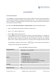
Maximum Call Duration Configure the maximum duration of the call (in seconds). The default setting is 0, which means no limit. Configure the warning time for the call using this outbound route. If set to Warning Time x seconds, the warning tone will be played to the caller when x seconds are left to end the call. Configure the warning repeat interval for the call using this outbound Warning Repeat Interval route.
Example: [12345-9] - Any digit from 1 to 9. Send This Call Through Trunk Select the trunk for this outbound rule. Use Trunk Allows the user to specify the number of digits that will be stripped from the beginning of the dialed string before the call is placed via the selected trunk. Example: Strip The users will dial 9 as the first digit of a long distance calls. However, 9 should not be sent out via analog lines and the PSTN line. In this case, 1 digit should be stripped before the call is placed.
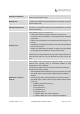
Click on to delete the inbound route. INBOUND RULE CONFIGURATIONS Table 57: Inbound Rule Configuration Parameters Trunks Select the trunk to configure the inbound rule. All patterns are prefixed with the "_". Special characters: X: Any Digit from 0-9. Z: Any Digit from 1-9. N: Any Digit from 2-9. ".": Wildcard. Match one or more characters. "!": Wildcard. Match zero or more characters immediately. DID Pattern Example: [12345-9] - Any digit from 1 to 9.
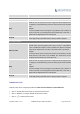
External Number By DID When "By DID" is used, the UCM6200 will look for the destination based on the number dialed, which could be local extensions, conference, call queue, ring group, paging/intercom group, IVR, voicemail groups and Fax extension as configured in "DID destination". If the dialed number matches the DID pattern, the call will be allowed to go through. Strip Prepend Configure the number of digits to be stripped from the beginning of the DID.
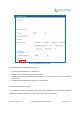
Figure 104: Inbound Route feature: Prepend The following example demonstrates the process, 1. If Trunk provides a DID pattern of 18005251163. 2. If Strip is set to 8, UCM6200 will strip the first 8 digits. 3. If Prepend is set to 2, UCM6200 will then prepend a 2 to the stripped number, now the number become 2163. 4. UCM6200 will now forward the incoming call to extension 2163.
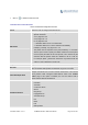
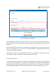
Figure 105: Inbound Route - Multiple Mode When Multiple Mode is enabled for the inbound route, the user can configure a “Default Destination” and a “Mode 1” destination for this route. By default, the call coming into this inbound route will be routed to the default destination. SIP end devices that have registered on the UCM6200 can dial feature code *62 to switch to inbound route “Mode 1” and dial feature code *61 to switch back to “Default Destination”.
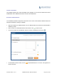
FAX WITH TWO MEDIA The UCM6200 supports Fax re-invite with multiple codec negotiation. If a Fax re-invite contains both T.38 and PCMA/PCMU codec, UCM6200 will choose T.38 codec over PCMA/PCMU. BLACKLIST CONFIGURATIONS In the UCM6200, Blacklist is supported for all inbound routes. Users could enable the Blacklist feature and manage the Blacklist by clicking on "Blacklist". Select the checkbox for "Blacklist Enable" to turn on Blacklist feature for all inbound routes. Blacklist is disabled by default.
Figure 107: Blacklist csv File -------------------------------------------------------------------------------------------------------------------------------------------Note: Users could also add a number to the Blacklist or remove a number from the Blacklist by dialing the feature code for "Blacklist Add' (default: *40) and "Blacklist Remove" (default: *41) from an extension. The feature code can be configured under Web GUI->PBX->Internal Options->Feature Codes. Firmware Version 1.0.0.
Firmware Version 1.0.0.
CONFERENCE BRIDGE The UCM6200 supports conference bridge allowing multiple bridges used at the same time: UCM6202/6204 supports up to 3 conference bridges allowing up to 25 simultaneous PSTN or IP participants. UCM6208 supports up to 6 conference bridges allowing up to 32 simultaneous PSTN or IP participants. The conference bridge configurations can be accessed under Web GUI->PBX->Call Features->Conference.
Note: Enable Caller Menu If "Public Mode" is enabled, the password is not required to join the conference bridge thus this field is invalid. The password has to be at least 4 characters. If enabled, conference participant could press the * key to access the conference bridge menu. The default setting is "No". If enabled, the calls in this conference bridge will be recorded Record Conference automatically in a .wav format file.
Select the music on hold class to be played in conference call. Music On Music On Hold Hold class can be set up under web UI->PBX->Internal Options->Music On Hold. Skip Authentication When If enabled, the invitation from Web GUI for a conference bridge with Inviting User via Trunk from password will skip the authentication for the invited users. The default Web GUI setting is "No". JOIN A CONFERENCE CALL Users could dial the conference bridge extension to join the conference.
A conference participant can invite other parties to the conference by dialing from the phone during the conference call. Please make sure option "Enable User Invite" is turned on for the conference bridge first. Enter 0 or 1 during the conference call. Follow the voice prompt to input the number of the party you would like to invite. A call will be sent to this number to join it into the conference.
Table 59: Conference Caller IVR Menu Conference Administrator IVR Menu 1 Mute/unmute yourself. 2 Lock/unlock the conference bridge. 3 Kick the last joined user from the conference. 4 Decrease the volume of the conference call. 5 Decrease your volume. 6 Increase the volume of the conference call. 7 Increase your volume. More options. 8 1: List all users currently in the conference call. 2: Kick all non-Administrator participants from the conference call.
To record the conference call, when the conference bridge is in idle, enable "Record Conference" from the conference bridge configuration dialog. Save the setting and apply the change. When the conference call starts, the call will be automatically recorded in .wav format. The recording files will be listed as below once available. Users could click on recording or click on to download the to delete the recording.
CONFERENCE SCHEDULE CONFERENCE SCHEUDLE CONFIGURATION Conference Schedule can be found under UCM6200 web UI->PBX->Call Features->Conference Schedule. Users can create, edit, view and delete a Conference Schedule. Click on “Create New Conference Schedule” to add a new Conference Schedule. Click on the scheduled conference to edit or delete the event.
Select the administrator of scheduled conference from selected extensions. Conference Administrator Note: “Public Mode” must be disabled from Conference Room Options tab. Local Extension Select available extensions from the list to attend scheduled conference. Select available extensions from the remote peer PBX. Remote Extension Note: “LDAP Sync” must be enabled on the UCM6200 in order to view remote extensions here. Add extensions that are not in the list (both local and remote list).
Press ‘3’ to drop all current multi-conference bridges Note: Conference Administrator is always allowed to access this menu. If this option is enabled, when a participant joins the conference room, participant’s name will be announced to all members in the conference Announce Callers room. Note: Option “Quiet Mode” and option “Announce Caller” cannot be enabled at the same time. If this option is enabled, no authentication is required for entering the conference room.
Figure 110: Conference Schedule Once the conference room is scheduled, at the kick time, all users will be removed from conference room and no extension is allowed to join the conference room anymore. At the scheduled conference time, UCM6200 will send INVITE to the extensions that have been selected for conference.
IVR CONFIGURE IVR IVR configurations can be accessed under the UCM6200 Web GUI->PBX->Call Features->IVR. Users could create, edit, view and delete an IVR. Click on "Create New IVR" to add a new IVR. Click on to edit the IVR configuration. Click on to delete the IVR. Table 61: IVR Configuration Parameters Basic Settings Name Configure the name of the IVR. Letters, digits, _ and - are allowed. Extension Enter the extension number for users to access the IVR.
allowed to go through. Select an audio file to play as the welcome prompt for the IVR. Click on Welcome Prompt "Prompt" to add additional audio file under web GUI->Internal Options->IVR Prompt. Configure the timeout between digit entries. After the user enters a digit, Digit Timeout the user needs to enter the next digit within the timeout. If no digit is detected within the timeout, the UCM6200 will consider the entries complete. The default timeout is 3 seconds.
Press 9 Fax Press * Custom Prompt Timeout Hangup Invalid DISA Dial By Name External Number Callback CREATE CUSTOM PROMPT To record new IVR prompt or upload IVR prompt to be used in IVR, click on “Prompt” next to the “Welcome Prompt” option and the users will be redirected to Custom Prompt page. Or users could go to Web GUI->PBX->Internal Options->Custom Prompt page directly.
Figure 112: Record New Custom Prompt Specify the IVR file name. Select the format (GSM or WAV) for the IVR prompt file to be recorded. Select the extension to receive the call from the UCM6200 to record the IVR prompt. Click the “Record” button. A request will be sent to the UCM6200. The UCM6200 will then call the extension for recording the IVR prompt from the phone. Pick up the call from the extension and start the recording following the voice prompt.
LANGUAGE SETTINGS FOR VOICE PROMPT The UCM6200 supports multiple languages in web GUI as well as system voice prompt. Currently, there are 16 languages supported in system voice prompt: English (United States), Arabic, Chinese, Dutch, English (United Kingdom), French, German, Greek, Hebrew, Italian, Polish, Portuguese, Russian, Spanish, Swedish and Turkish. English (United States) and Chinese voice prompts are built in with the UCM6200 already.
Figure 115: Voice Prompt Package List Click on to download the language to the UCM6200. The installation will be automatically started once the downloading is finished. Figure 116: New Voice Prompt Language Added A new language option will be displayed after successfully installed. Users then could select it to apply in the UCM6200 system voice prompt or delete it from the UCM6200. Firmware Version 1.0.0.
CUSTOMIZE SPECIFIC PROMPT On the UCM6200, if the user needs to replace some specific customized prompt, the user can upload a single specific customized prompt from web UI->PBX->Internal Options->Language instead of the entire language pack. Figure 117: Upload Single Voice Prompt for Entire Language Pack Firmware Version 1.0.0.
Firmware Version 1.0.0.
VOICEMAIL CONFIGURE VOICEMAIL If the voicemail is enabled for UCM6200 extensions, the configurations of the voicemail can be globally set up and managed under Web GUI->PBX->Call Features->Voicemail. Table 62: Voicemail Settings Max Greeting Configure the maximum number of seconds for the voicemail greeting. The default setting is 60 seconds. If enabled, the caller can press 0 to exit the voicemail application and Dial ‘0’ For Operator connect to the configured operator’s extension.
is "No". Announce Message Duration If enabled, the message duration will be announced at the beginning of the voicemail message. The default setting is "No". If enabled, a brief introduction (received time, received from, and etc) of Play Envelope each message will be played when accessed from the voicemail application. The default setting is "Yes".
1 - Send a reply 3- 2 - Call the person who sent this message Advanced 3 - Hear the message envelop options 4 - Leave a message * - Return to the main menu 1 - Accept this recording 1 - Record your unavailable message 2 - Listen to it 3 - Re-record your message 1 - Accept this recording 2 - Record your busy message 2 - Listen to it 3 - Re-record your message 1 - Accept this recording 0 - Mailbox options 3 - Record your name 2 - Listen to it 3 - Re-record your message 1 - Accept this recording 4
${VM_DUR}: The duration of the voicemail message ${VM_MAILBOX}: The recipient's extension ${VM_CALLERID}: The caller ID of the person who has left the message ${VM_MSGNUM}: The number of messages in the mailbox ${VM_DATE}: The date and time when the message is left Figure 118: Voicemail Email Settings Click on "Load Default Settings" button to view the default template as an example.
Figure 119: Voicemail Group Table 65: Voicemail Group Settings Extension Name Voicemail Password Email Address Enter the Voicemail Group Extension. The voicemail messages left to this extension will be forwarded to all the voicemail group members. Configure the Name to identify the voicemail group. Letters, digits, _ and are allowed. Configure the voicemail password for the users to check voicemail messages. Configure the Email address for the voicemail group extension.
Firmware Version 1.0.0.
RING GROUP The UCM6200 supports ring group feature with different ring strategies applied to the ring group members. This section describes the ring group configuration on the UCM6200. CONFIGURE RING GROUP Ring group settings can be accessed via Web GUI->PBX->Call Features->Ring Group. Figure 120: Ring Group Click on “Create New Ring Group” to add ring group. Click on to edit the ring group. The following table shows the ring group configuration parameters. Click on to delete the ring group.
This option is to set a custom prompt for a ring group to announce to Custom Prompt caller. Click on ‘Prompt’, it will direct to the page PBX->Internal Options->Custom Prompt, where users could record new prompt or upload prompt files. Configure the number of seconds to ring each member. If set to 0, it will keep ringing. The default setting is 30 seconds. Ring Timeout on Each Member Note: The actual ring timeout might be overridden by users if the phone has ring timeout settings as well.
Figure 121: Ring Group Configuration REMOTE EXTENSION IN RING GROUP Remote extensions from the peer trunk of a remote UCM6200 can be included in the ring group with local extension. An example of Ring Group with peer extensions is presented in the following: 1. Creating SIP Peer Trunk between both UCM6200_A and UCM6200_B. SIP Trunk can be found under web UI-> PBX-> Basic/Call Routes-> VoIP Trunks. Also, please configure their Inbound/Outbound routes accordingly. 2.
Figure 122: Sync LDAP Server option 3. In case if LDAP server doesn’t sync automatically, user can manually sync LDAP server. Under VoIP Trunks page, click sync button shown in the following figure to manually sync LDAP contacts from peer UCM6200. Figure 123: Manually Sync LDAP Server Firmware Version 1.0.0.
4. Under Ring Groups setting page, click . Ring Groups can be found under web UI-> PBX-> Call Features-> Ring Groups. 5. If LDAP server is synced correctly, Available LDAP Numbers box will display available remote extensions that can be included in the current ring group. Please also make sure the extensions in the peer UCM6200 can be included into that UCM6200’s LDAP contact. Figure 124: Ring Group Remote Extension Firmware Version 1.0.0.
Firmware Version 1.0.0.
PAGING AND INTERCOM GROUP Paging and Intercom Group can be used to make an announcement over the speaker on a group of phones. Targeted phones will answer immediately using speaker. The UCM6200 paging and intercom can be used via feature code to a single extension or a paging/intercom group. This sections describes the configuration of paging/intercom group under Web GUI->PBX->Call Features->Paging/Intercom.
Click on to edit the paging/intercom group. Click on to delete the paging/intercom group. Click on "Paging/Intercom Group Settings" to edit Alert-Info Header. This header will be included in the SIP INVITE message sent to the callee in paging/intercom call. Figure 126: Page/Intercom Group Settings The UCM6200 has pre-configured paging/intercom feature code. By default, the Paging Prefix is *81 and the Intercom Prefix is *80.
CALL QUEUE The UCM6200 supports call queue by using static agents or dynamic agents. Call Queue system can accept more calls than the available agents. Incoming calls will be held until next representative is available in the system. This section describes the configuration of call queue under Web GUI->PBX->Call Features->Call Queue. CONFIGURE CALL QUEUE Call queue settings can be accessed via Web GUI->PBX->Call Features->Call Queue.
Least Recent Ring the agent who has been called the least recently. Fewest Calls Ring the agent with the fewest completed calls. Random Ring a random agent. Round Robin Ring the agents in Round Robin scheduling with memory. The default setting is "Ring All". Select the Music On Hold class for the call queue. Music On Hold Note: Music On Hold classes can be managed from Web GUI-> PBX->Internal Options->Music On Hold.
after the last call on the agent is completed. If set to 0, there will be no delay between calls to the queue. The default setting is 15 seconds. Configure the maximum number of calls to be queued at once. This number does not include calls that have been connected with agents. It Max Queue Length only includes calls not connected yet. The default setting is 0, which means unlimited.
Figure 128: Agent Login Settings For example, if the call queue extension is 6500, Agent Login Extension Postfix is * and Agent Logout Extension Postfix is **, users could dial 6500* to login to the call queue as dynamic agent and dial 6500** to logout from the call queue. Dynamic agent doesn't need to be listed as static agent and can log in/log out at any time. Call queue feature code "Agent Pause" and "Agent Unpause" can be configured under Web GUI->PBX->Internal Options->Feature Codes.
EXTENSION GROUPS The UCM6200 extension group feature allows users to assign and categorize extensions in different groups to better manage the configurations on the UCM6200. For example, when configuring "Enable Filter on Source Caller ID", users could select a group instead of each person's extension to assign. This feature simplifies the configuration process and helps manage and categorize the extensions for business environment.
USING EXTENSION GROUPS Here is an example where the extension group can be used. Go to Web GUI->PBX->Basic/Call Routes->Outbound Routes and select "Enable Filter on Source Caller ID". Both single extensions and extension groups will show up for users to select. Figure 130: Select Extension Group in Outbound Route Firmware Version 1.0.0.
PICKUP GROUPS The UCM6200 supports pickup group feature which allows users to pick up incoming calls for other extensions if they are in the same pickup group, by dialing "Pickup Extension" feature code (by default *8). CONFIGURE PICKUP GROUPS Pickup groups can be configured via Web GUI->PBX->Call Features->Pickup Groups. Click on "Create New Pickup Group" to create a new pickup group. Click on to edit the pickup group. Select extensions from the list on the left side to the right side.
Figure 132: Edit Pickup Feature Code Firmware Version 1.0.0.
MUSIC ON HOLD Music On Hold settings can be accessed via Web GUI->PBX->Internal Options->Music On Hold. In this page, users could configure music on hold class and upload music files. The "default" Music On Hold class already has 5 audio files defined for users to use. Figure 133: Music On Hold Default Class Click on "Create New MOH Class" to add a new Music On Hold class. Click on to configure the MOH class sort method to be "Alpha" or "Random" for the sound files.
Click on to select music file from local PC and click on to start uploading. The music file uploaded has to be 8 KHz Mono format with size smaller than 5M. Click on Select the sound files and click on next to the sound file to delete it from the selected Music On Hold Class. to delete all selected music on hold files.
FAX/T.38 The UCM6200 supports T.30/T.38 Fax and Fax Pass-through. It can convert the received Fax to PDF format and send it to the configured Email address. Fax/T.38 settings can be accessed via Web GUI->PBX->Internal Options->FAX/T.38. The list of received Fax files will be displayed in the same web page for users to view, retrieve and delete. CONFIGURE FAX/T.38 Click on "Create New Fax Extension". In the popped up window, fill the extension, name and Email address to send the received Fax to.
The extension's Email address or the Fax's default Email address needs to be configured in order to receive Fax from Email. If neither of them is configured, Fax will be not be received from Email. Fill in the "Subject:" and "Message:" content, to be used in the Email when sending the Fax to the users.
Figure 134: Configure Analog Trunk without Fax Detection 5. Go to UCM6200 web GUI->PBX->Basic/Call Routes->Extensions page. 6. Create or edit the extension for FXS port. Analog Station: Select FXS port to be assigned to the extension. By default, it's set to "None". Once selected, analog related settings for this extension will show up in "Analog Settings" section. Figure 135: Configure Extension for Fax Machine: FXS Extension Firmware Version 1.0.0.
Figure 136: Configure Extension for Fax Machine: Analog Settings 7. Go to web GUI->PBX->Basic/Call Routes->Inbound Routes page. 8. Create an inbound route to use the Fax analog trunk. Select the created extension for Fax machine in step 4 as the default destination. Figure 137: Configure Inbound Rule for Fax Firmware Version 1.0.0.
Now the Fax configuration is done. When there is an incoming Fax calling to the PSTN number for the FXO port, it will send the Fax to the Fax machine. SAMPLE CONFIGURATION FOR FAX‐TO‐EMAIL The following instructions describe a sample configuration on how to use Fax-to-Email feature on the UCM6200. 1. Connect PSTN line to the UCM6200 FXO port. 2. Go to UCM6200 web GUI->Internal Options->Fax/T.38 page. Create a new Fax extension. Figure 138: Create Fax Extension 3.
Figure 139: Inbound Route to Fax Extension 5. Once successfully configured, the incoming Fax from external Fax machine to the PSTN line number will be converted to PDF file and sent to the Email address Faxtest@ucm6200mycompany.com as attachment. Firmware Version 1.0.0.
ASTERISK MANAGER INTERFACE (RESTRICTED ACCESS) The UCM6200 supports Asterisk Manager Interface (AMI) with restricted access. AMI allows a client program to connect to an Asterisk instance commands or read events over a TCP/IP stream. It’s particularly useful when the system admin tries to track the state of a telephony client inside Asterisk. User could configure AMI parameters on UCM6200 web GUI->PBX->Internal Options->AMI.
Firmware Version 1.0.0.
BUSY CAMP‐ON The UCM6200 supports busy camp-on/call completion feature that allows the PBX to camp on a called party and inform the caller as soon as the called party becomes available given the previous attempted call has failed. The configuration and instructions on how to use busy camp-on/call completion feature can be found in the following guide: http://www.grandstream.com/sites/default/files/Resources/ucm6200_busy_camp_on_guide.pdf Firmware Version 1.0.0.
Firmware Version 1.0.0.
FOLLOW ME Follow Me is a feature on the UCM6200 that allows users to direct calls to other phone numbers and have them ring all at once or one after the other. Calls can be directed to users’ home phone, office phone, mobile and etc. The calls will get to the user no matter where they are. Follow Me option can be found under web GUI-> PBX-> Call Features->Follow Me. To configure follow me: Click on "Create New Follow Me" and then select an extension to be configured with Follow Me.
Click on “Add Follow Me Number” to add local extensions or external numbers to be called after ringing the extension selected in the first step. Once created, it will be displayed on the follow me web page list. Click on configuration. Click on to edit the Follow Me to delete the Follow Me. The following table shows the Follow Me configuration parameters. Table 70: Follow Me Settings Enable Configure to enable or disable Follow Me for this user.
Click on “Follow Me Options” to enable or disable the options listed in the following table. Table 71: Follow Me Options Playback Incoming Status If enabled, the PBX will playback the incoming status message before Message starting the Follow Me steps. Record the Caller’s Name If enabled, the PBX will record the caller’s name from the phone so it can be announced to the callee in each step.
Firmware Version 1.0.0.
ONE‐KEY DIAL The UCM6200 supports One-Key Dial that allows users to call a certain destination by pressing one digit 0 to 9 on the keypad. This creates a system-wide speed dial access for all the extensions on the UCM6200. To enable One-Key Dial, on the UCM6200 web GUI, go to page PBX->Call Features->One-Key Dial. Figure 142: Configure One-Key Dial User should first decide a digit used for One-Key Dial and check the option “Enable Destination” for the digit.
Figure 143: One-Key Dial Destinations Firmware Version 1.0.0.
DISA In many situations the user will find the need to access his own IP PBX resources but he is not physically near one of his extensions. However, he does have access to his own cell phone. In this case we can use what is commonly known as DISA (Direct Inward System Access). Under this scenario the user will be able to call from the outside, whether it’s using his cell phone, pay phone, regular PSTN, etc.
Configure the permission level for DISA. The available permissions are "Internal", "Local", "National" and "International" from the lowest level to the highest level. The default setting is "Internal". If the user tries to dial Permission outbound calls after dialing into the DISA, the UCM6200 will compared the DISA's permission level with the outbound route's privilege level.
CALLBACK FEATURE Callback is mainly designed for users who often use their mobile phones to make long distance or international calls which may have high service charges. The callback feature provides an economic solution for reduce the cost from this. The callback feature works as follows: 1. Configure a new callback on the UCM6200. 2. On the UCM6200, configure destination of the inbound route for analog trunk to callback. 3. Save and apply the settings. 4.
Delay Before Callback Configure the number of seconds to be delayed before calling back the user. Configure the destination which the callback will direct the caller to. Two destinations are available: Destination IVR DISA The caller can then enter the desired number to dial out via UCM6200 trunk. Firmware Version 1.0.0.
BLF AND EVENT LIST BLF The UCM6200 supports BLF monitoring for extensions, ring group, call queue, conference room and parking lot. For example, on the user's phone, configure the parking lot number 701 as the BLF monitored number. When there is a parked call on 701, the LED for this BLF key will light up in red, meaning a call is parked against this parking lot. Pressing this BLF key can pick up the call from this parking lot.
manually enter the remote extensions under "Special Extensions" field. Manually enter the remote extensions in the peer/register trunk to be Special Extensions monitored in the event list. Valid format: 5000,5001,9000 Figure 145: Create New Event List Remote extension monitoring works on the UCM6200 via event list BLF, among Peer SIP trunks or Register SIP trunks (register to each other). Therefore, please properly configure SIP trunks on the UCM6200 first before using remote BLF feature.
-------------------------------------------------------------------------------------------------------------------------------------------Note: To configure LDAP sync, please go to UCM6200 web GUI->PBX->Basic/Call Routes->VoIP Trunk. You will see "Sync LDAP Enable" option. Once enabled, please configure password information for the remote peer UCM6200 to connect to the local UCM6200. Additional information such as port number, LDAP outbound rule, LDAP Dialed Prefix will also be required.
Firmware Version 1.0.0.
DIAL BY NAME Dial By Name is a feature on the PBX that allows caller to search a person by first or last name via his/her phone's keypad. The administrator can define the Dial By Name directory including the desired extensions in the directory and the searching type by "first name" or "last name". After dialing in, the PBX IVR/Auto Attendant will guide the caller to spell the digits to find the person in the Dial By Name directory.
1. Group Name Enter the Group Name. This is to identify the Dial By Name group. The Dial By Name group can be used as the destination for inbound route and key pressing event for IVR. The group name defined here will show up in the destination list when configuring IVR and inbound route. If Dial By Name is set as a key pressing event for IVR, user could use ‘*’ to exit from Dial By Name, then re-enter IVR and start a new event. The following example shows how to use this option.
Figure 148: Dial By Name Group In Inbound Rule 2. Extension Configure the direct dial extension for the Dial By Name group. 3. Available Extensions/Selected Extensions Select available extensions from the left side to the right side as the directory for the Dial By Name group. Only the selected extensions here can be reached by the Dial By Name IVR when dialing into this group.
Figure 149: Configure Extension First Name and Last Name 4. Query Type Specify the query type. This defines how the caller will need to enter to search the directory. By First Name: enter the first 3 digits of the first name to search the directory. By Last Name: enter the first 3 digits of the last name to search the directory. By Full Name: enter the first 3 digits of the first name or last name to search the directory. 5. Select Type Specify the select type on the searching result.
ACTIVE CALLS AND MONITOR The active calls on the UCM6200 are displayed in web UI->Status->Active Calls page. Users can monitor the status, hang up the call as well as barge in the active calls in real time manner. ACTIVE CALLS STATUS To view the status of active calls, navigate to web GUI->Status->Active Calls. The following figure shows extension 1000 is calling 1001. 1001 is ringing.
In active call web page, click on to refresh the active call status. HANG UP ACTIVE CALLS To hang up an active call, click on icon in the active call dialog. Users can also click on to hang up all active calls. CALL MONITOR During an active call, click on icon and the monitor dialog will pop up. Figure 152: Configure to Monitor an Active Call In the “Monitor” dialog, configure the following to monitor an active call: 1.
4. Enable or disable “Require Confirmation” option. If enabled, the confirmation of the invited monitor’s extension is required before the active call can be monitored. This option can be used to avoid adding participant who has auto-answer configured or call forwarded to voicemail. 5. Click on “Add”. An INVITE will be sent to the monitor’s extension. The monitor can answer the call and start monitoring. If “Require Confirmation” is enabled, the user will be asked to confirm to monitor the call.
Firmware Version 1.0.0.
CALL FEATURES The UCM6200 supports call recording, transfer, call forward, call park and other call features via feature code. This section lists all the feature codes in the UCM6200 and describes how to use the call features. FEATURE CODES Table 75: UCM6200 Feature Codes Feature Maps Default code: #1. Enter the code during active call. After hearing "Transfer", you will hear dial tone. Enter the number to transfer to. Then the user will be disconnected and transfer is completed.
Default code: #72. Enter the code during active call to park the call. Options Call Park Disable Allow Caller: Enable the feature code on caller side only. Allow Callee: Enable the feature code on callee side only. Allow Both: Enable the feature code on both caller and callee. Default code: *3. Enter the code followed by # or SEND to start recording the audio call and the UCM6200 will mix the streams natively on the fly as the call is in progress.
Feature Code Digits Timeout Call Park Parked Lots Default Setting: 1000. Configure the maximum interval (in milliseconds) between the digits input to activate the feature code. Default Extension: 700. During an active call, initiate blind transfer and then enter this code to park the call. Default Extension: 701-720. These are the extensions where the calls will be parked, i.e., parking lots that the parked calls can be retrieved.
Blacklist Add Blacklist Remove Call Pickup on Ringing Pickup Extension Default Code: *40. To add a number to blacklist for inbound route, dial *40 and follow the voice prompt to enter the number. Default Code: *41. To remove a number from current blacklist for inbound route, dial *41 and follow the voice prompt to remove the number. Default Code: **. To pick up a call for any extension xxxx, enter the code followed by the extension number xxxx. Default Code: *8.
This is the feature code to join in on the call to assist both parties. Barge Spy The default setting is *56. If enabled, user can switch between different inbound route modes Enable Inbound Multiple Mode with feature code. By default, this option is disabled. This feature code is used to switch inbound route mode to default Inbound Default Mode mode. The default setting is *61. This feature code is used to switch inbound route mode to mode 1. Inbound Mode 1 The default setting is *62.
The above recorded call's recording files are also listed under the UCM6200 web GUI->CDR->Recording Files. Figure 154: Download Recording File from Recording Files Page CALL PARK The UCM6200 provides call park and call pickup features via feature code. PARK A CALL There are two feature codes that can be used to park the call. Feature Maps->Call Park (Default code #72) During an active call, press #72 and the call will be parked.
Assume a call is on-going between extension A and extension B, user could dial the feature code from extension C to listen on their call (*54 by default), whisper to one side (*55 by default), or barge into the call (*56 by default). Then the user will be asked to enter the number to call, which should be either side of the active call, extension A or B in this example.
Firmware Version 1.0.0.
INTERNAL OPTIONS This section describes internal options that haven't been mentioned in previous sections yet. The settings in this section can be applied globally to the UCM6200, including general configurations, jitter buffer, RTP settings, ports config and STUN monitor. The options can be accessed via Web GUI->PBX->Internal Options-> General.
digits, with a minimum length of 4 digits. Repetitive digits pattern (such as 0000, 1111, 1234, 2345, and etc), or common digits pattern (such as 111222, 321321 and etc) are not allowed to be configured as password. 2. Password for extension registration, web GUI admin login, LDAP and LDAP sync requires alphanumeric characters containing at least two categories of the following, with a minimum length of 4 characters.
Auto Provision Extensions: 5000-6299 This sets the range for "Zero Config Extension Segment" which is the extensions can be assigned on the UCM6200 to provision the end device.
INTERNAL OPTIONS/RTP SETTINGS Table 78: Internal Options/RTP Settings RTP Start Configure the RTP port starting number. The default setting is 10000. RTP End Configure the RTP port ending address. The default setting is 20000. Configure to enable or disable strict RTP protection. If enabled, RTP Strict RTP packets that do not come from the source of the RTP stream will be dropped. The default setting is "Disable". RTP Checksums Configure to enable or disable RTP Checksums on RTP traffic.
G.721 Compatible G.726 Configure to enable/disable G.721 compatible. The default setting is Yes. Configure the payload type for G.726 if "G.721 Compatible" is disabled. The default setting is 111. iLBC Configure the payload type for iLBC. The default setting is 97. H.264 Configure the payload type for H.264. The default setting is 99. H.263P Configure the payload type for H.263+. The default setting is 100 103. VP8 Configure the payload type for VP8. The default settings is 108.
Firmware Version 1.0.0.
IAX SETTINGS The UCM6200 IAX global settings can be accessed via Web GUI->PBX->IAX Settings. IAX SETTINGS/GENERAL Table 80: IAX Settings/General Bind Port Bind Address IAX1 Compatibility Configure the port number that the IAX2 will be allowed to listen to. The default setting is 4569. Configure the address that the IAX2 will be forced to bind to. The default setting is 0.0.0.0, which means all addresses. Select to configure IAX1 compatibility. The default setting is "No".
If set to "yes", the connection will be terminated if ACK for the NEW Auto Kill message is not received within 2000ms. Users could also specify number (in milliseconds) in addition to "yes" and "no". The default setting is "yes". Authentication Debugging If enabled, authentication traffic in debugging will not show. The default setting is "No". Configure codec negotiation priority. The default setting is "Reqonly". Codec Priority Caller Consider the callers preferred order ahead of the host's.
SIP SETTINGS The UCM6200 SIP global settings can be accessed via Web GUI->PBX->SIP Settings. SIP SETTINGS/GENERAL Table 83: SIP Settings/General Realm For Digest Authentication Bind UDP Port Bind IP Address Configure the host name or domain name for the UCM6200. Realms MUST be globally unique according to RFC3261. The default setting is Grandstream. Configure the UDP port used for SIP. The default setting is 5060. Configure the IP address to bind to. The default setting is 0.0.0.
Support SIP Video Select to enable video support in SIP calls. The default setting is "Yes". If enabled, when rejecting an incoming INVITE or REGISTER request, the UCM6200 will always reject with "401 Unauthorized" instead of notifying Reject Non-Matching INVITE the requester whether there is a matching user or peer for the request. This reduces the ability of an attacker to scan for valid SIP usernames. The default setting is "No".
Note: The IP address must match the common name (hostname) in the certificate. Please do not bind a TLS socket to multiple IP addresses. For details on how to construct a certificate for SIP, please refer to the following document: http://tools.ietf.org/html/draft-ietf-sip-domain-certs TLS Client Protocol TLS Do Not Verify Select the TLS protocol for outbound client connections. The default setting is TLSv1. If enabled, the TLS server's certificate won't be verified when acting as a client.
External TCP Port External TLS Port Configure the externally mapped TCP port when the UCM6200 is behind a static NAT or PAT. Configures the externally mapped TLS port when UCM6200 is behind a static NAT or PAT. Specify a list of network addresses that are considered inside of the NAT network. Multiple entries are allowed. If not configured, the external IP Local Network Address address will not be set correctly. A sample configuration could be as follows: 192.168.0.
seconds), the call will be terminated. This value of RTP Hold Timeout should be larger than RTP Timeout. The default setting is no timeout. Trust Remote Party ID Send Remote Party ID Configure whether the Remote-Party-ID should be trusted. The default setting is "No". Configure whether the Remote-Party-ID should be sent or not. The default setting is "No". Configure whether the UCM6200 should generate inband ringing or not. The default setting is "Never".
Firmware Version 1.0.0.
PORTS CONFIG The analog hardware (FXS port and FXO port) on the UCM6200 will be listed in this page. Click on to edit signaling preference for FXS port or configure ACIM settings for FXO port. Select "Loop Start" or "Kewl Start" for each FXS port. And then click on "Update" to save the change. Figure 155: FXS Ports Signaling Preference For FXO port, users could manually enter the ACIM settings by selecting the value from dropdown list for each port.
Threshold, Current Limiting, TIP/RING voltage adjustment, Minimum Operational Loop Current, and AC Impedance as predefined for your country's analog line characteristics. The default setting is "United States of America (USA)". Select country to set the On Hook Speed, Ringer Impedance, Ringer Threshold, Current Limiting, TIP/RING voltage adjustment, Minimum FXS Opermode Operational Loop Current, and AC Impedance as predefined for your country's analog line characteristics.
VALUE‐ADDED FEATURES FAX SENDING The UCM6200 supports sending Fax via web UI access. This feature can be found on web UI->PBX->Value-added Features->Fax Sending page. In order to send fax, pre-setup for analog trunk and outbound route is required. Please refer to [ANALOG TRUNKS], [VOIP TRUNKS] and [OUTBOUND ROUTES] sections for configuring analog trunk and outbound route.
Figure 158: Announcements Center ANNOUNCEMENTS CENTER SETTINGS Table 90: Announcements Center Settings Name Configure a name for the newly created Announcements Center to identify this announcement center. Enter a code number for the custom prompt. This code will be used in combination with the group number. For example, if the code is 55, and group number is 666. The user can dial 55666 to send prompt 55 to all Code members in group 666.
Configure the group number. The group number is used in combination with the code. For example, if group number is 666, and code is 55. The user can dial 55666 to send prompt 55 to all members in group 666. Number Note: The combination number must not conflict with any number in the system such as extension number or conference number. Announcements Center feature can be found under web UI->PBX->Value-added Features-> Announcements Center. The following example demonstrates the usage of this feature. 1.
a new Prompt, please click “Prompt” link and follow the instructions in that page. Figure 160: Announcements Center Code Configuration Code and Group number are used together to direct specified message to the target group. All extensions in the group will receive the message. For example, we can send code 55 to group 666 by dialing 55666 from any extension registered to the UCM6200.
STATUS AND REPORTING PBX STATUS The UCM6200 monitors the status for Trunks, Extensions, Queues, Conference Rooms, Interfaces and Parking lot. It presents administrators the real time status in different sections under web GUI->Status->PBX Status. Figure 162: Status->PBX Status TRUNKS Users could see all the configured trunk status in this section. Figure 163: Trunk Status Table 92: Trunk Status Display trunk status.
Unmonitored: QUALIFY feature is not turned on to be monitored. Reachable: The hostname can be reached. SIP Register trunk status: Registered Unrecognized Trunk Trunks Display trunk name Display trunk Type: Type Analog SIP IAX Username Display username for this trunk. Port/Hostname/IP Display Port for analog trunk, or Hostname/IP for VoIP (SIP/IAX) trunk.
Table 93: Extension Status Display extension number (including feature code). The color indicator has the following definitions. Status Green: Free Blue: Ringing Yellow: In Use Grey: Unavailable Extension Display the extension number. Name/Label First name and last name of the extension. Display message status for the extension. Example: 2/4/1 Message Description: There are 2 urgent messages, 4 messages in total and 1 message that has been already read. Displays extension type.
Figure 165: Queue Status The current call status (caller ID, duration), agent status, service level, calls summary (completed/abandoned) are shown for the call queue. The agent status is defined as below. Table 94: Agent Status The agent is available/idle. The agent is ringing. The agent is talking/busy. The agent has been logged out.
Figure 166: Conference Room Status Other operations are also available in conference room status section: Click on "Conference Rooms", the web page will redirect to conference room configuration page which can also be accessed via web GUI->PBX->Call Features->Conference. Click on Click on [ + ] to expand the conference room details. Click on [ - ] to hide the conference room details. to refresh the conference room status.
LAN/WAN connected. LAN/WAN not configured. LAN/WAN disconnected. FXS/FXO connected. FXS/FXO waiting. FXS/FXO busy. FXS/FXO not configured. FXS/FXO disconnected. Other operations are also available in interface status section: Click on "Interfaces Status", the web page will redirect to ports configuration page which can also be accessed via web GUI->PBX->Internal Options->Ports Config. Click on Click on [ + ] to expand the interface details. Click on [ - ] to hide the interface details.
reaches 0, the caller who parks the call will be called back. Other operations are also available in parking lot status section: Click on "Parking Lot", the web page will redirect to feature codes page which can also be accessed via web GUI->PBX->Internal Options->Feature Codes. Click on Click on [ + ] to expand the parking lot details. Click on [ - ] to hide the parking details. to refresh the parking lot status.
Recovery Recovery version. NETWORK Under Web GUI->Status->System Status->Network, users could check the network information for the UCM6200. Please see details in the following table. Table 98: System Status->Network Status -> System Status -> Network MAC Address Global unique ID of device, in HEX format. The MAC address can be found on the label coming with original box and on the label located on the bottom of the device. IP Address IP address. Gateway Default gateway address.
Figure 169: System Status->Storage Usage RESOURCE USAGE When configuring and managing the UCM6200, users could access resource usage information to estimate the current usage and allocate the resources accordingly. Under web UI->Status->System Status->Resource Usage, the current CPU usage and Memory usage are shown in the pie chart. Figure 170: System Status->Resource Usage Firmware Version 1.0.0.
SYSTEM EVENTS The UCM6200 can monitor important system events, log the alerts and send Email notifications to the system administrator. ALERT EVENTS LIST The system alert events list can be found under Web GUI->Status->System Events->Alert Events List.
Detect Cycle: The UCM6200 will perform the internal disk usage detection based on this cycle. Users can enter the number and then select second(s)/minute(s)/hour(s)/day(s) to configure the cycle. Alert Threshold: If the detected value exceeds the threshold (in percentage), the UCM6200 system will send the alert. 2. Memory Usage Figure 172: System Events->Alert Events Lists: Memory Usage Detect Cycle: The UCM6200 will perform the memory usage detection based on this cycle.
Detect Cycle: The UCM will detect the event at each cycle based on the specified time. Users can enter the number and then select second(s)/minute(s)/hour(s)/day(s) to configure the cycle. Click on the switch to turn on/off the alert and Email notification for the event. Users could also select the checkbox for each event and then click on button "Alert On", "Alert Off", "Email Notification On", "Email Notification Off" to control the alert and Email notification configuration.
Figure 176: Filter for Alert Log ALERT CONTACT Users could add administrator's Email address under Web GUI->Status->System Events->Alert Contact to send the alert notification to. Up to 10 Email addresses can be added. CDR A Call Detail Record (CDR) is a data record produced by telephone exchange activities or other telecommunications equipment documenting the details of a phone call that passed through the PBX. The CDR is composed of the following data fields on the UCM6200. Start Time.
Figure 177: CDR Filter Table 99: CDR Filter Criteria Inbound calls Inbound calls are calls originated from a non-internal source (like a VoIP trunk) and sent to an internal extension. Outbound calls Outbound calls are calls sent to a non-internal source (like a VoIP trunk) from an internal extension. Internal calls Internal calls are calls from one internal extension to another extension, which are not sent over a trunk.
be filtered out. Callee Number Enter the callee number to filter the CDR report. CDR with the matching callee number will be filtered out. The call report will display as the following figure shows. Figure 178: Call Report Users could perform the following operations on the call report. Sort Click on the header of the column to sort by this category. For example, clicking on "Start Time" will sort the report according to start time. Clicking on "Start Time" again will reverse the order.
Automatic Download CDR Records User could configure the UCM6200 to automatically download the CDR records and send the records to an Email address. Click on “Automatic Download Settings”, and configure the parameters in the dialog below. Figure 180: Automatic Download Settings To receive CDR record automatically from Email, check “Enable” and select a time period “By Day” “By Week” or “By Month” for the automatic download period. Make sure you have entered an Email address to receive the CDR records.
Figure 182: Detailed CDR Information DOWNLOADED CDR FILE The downloaded CDR (.csv file) has different format from the web UI CDR. Here are some descriptions. Call From, Call To "Call From": the caller ID. "Call To": the callee ID. If "Call From" shows empty, "Call To" shows "s" (see highlight part in the picture below) and the "Source Channel" contains "DAHDI", this means the call is from FXO/PSTN line.
Figure 184: Downloaded CDR File Sample - Source Channel and Dest Channel 1 DAHDI means it is an analog call, FXO or FXS. For UCM6202, DAHDI/(1-2) are FXO ports, and DAHDI(3-4) are FXS ports. For UCM6204, DAHDI/(1-4) are FXO ports, and DAHDI(5-6) are FXS ports. For UCM6208, DAHDI/(1-8) are FXO ports, and DAHDI(9-10) are FXS ports. Sample 2: Figure 185: Downloaded CDR File Sample - Source Channel and Dest Channel 2 "SIP" means it's a SIP call.
STATISTICS CDR Statistics is an additional feature on the UCM6200 which provides users a visual overview of the call report across the time frame. Users can filter with different criteria to generate the statistics chart. Figure 187: CDR Statistics Table 100: CDR Statistics Filter Criteria Trunk Type Select one of the following trunk type. Call Type Time Range All SIP Calls PSTN Calls Select one or more in the following checkboxes.
Figure 188: CDR->Recording Files Click on “Delete Selected Recording Files” to delete the recording files. Click on “Delete All Recording Files” to delete all recording files. Click on to download the recording file in .wav format. Click on to delete the recording file. To sort the recording file, click on the title "Caller", "Callee" or "Call Time" for the corresponding column. Click on the title again can switch the sorting mode between ascending order or descending order.
Username Configure the Username for API Authentication. Password Configure the Password for API Authentication. Permitted Specify a list of IP addresses permitted by API. This creates an AIP-specific access control list. Multiple entries are allowed. For example, "192.168.40.3/255.255.255.255" denies access from all IP addresses except 192.168.40.3. The default setting is blank, meaning all IPs will be denied. Users must set permitted IP address before connecting to the API.
Firmware Version 1.0.0.
UPGRADING AND MAINTENANCE UPGRADING The UCM6200 can be upgraded to a new firmware version remotely or locally. This section describes how to upgrade your UCM6200 via network or local upload. UPGRADING VIA NETWORK The UCM6200 can be upgraded via TFTP/HTTP/HTTPS by configuring the URL/IP Address for the TFTP/HTTP/HTTPS server and selecting a download method. Configure a valid URL for TFTP, HTTP or HTTPS; the server name can be FQDN or IP address. Examples of valid URLs: firmware.grandstream.
Table 102: Network Upgrade Configuration Upgrade Via Allow users to choose the firmware upgrade method: TFTP, HTTP or HTTPS. Firmware Server Path Define the server path for the firmware server. Firmware File Prefix If configured, only the firmware with the matching encrypted prefix will be downloaded and flashed into the UCM6200. Firmware File Suffix If configured, only the firmware with the matching encrypted postfix will be downloaded and flashed into the UCM6200.
Click on to start upgrading. Figure 191: Upgrading Firmware Files Wait until the upgrading process is successful and a window will be popped up in the Web GUI. Figure 192: Reboot UCM6200 Click on "OK" to reboot the UCM6200 and check the firmware version after it boots up. -------------------------------------------------------------------------------------------------------------------------------------------Note: Please do not interrupt or power cycle the UCM6200 during upgrading process.
NO LOCAL FIRMWARE SERVERS Service providers should maintain their own firmware upgrade servers. For users who do not have TFTP/HTTP/HTTPS server, some free windows version TFTP servers are available for download from http://www.solarwinds.com/products/freetools/free_tftp_server.aspx http://tftpd32.jounin.net Please check our website at http://www.grandstream.com/support/firmware for latest firmware. Instructions for local firmware upgrade via TFTP: 1.
Figure 193: Create New Backup 1. Choose the type(s) of files to be included in the backup. 2. Choose where to store the backup file: USB Disk, SD Card or Local. 3. Name the backup file. 4. Click on "Backup" to start backup. Once the backup is done, the list of the backups will be displayed with date and time in the web page. Users can download , restore , or delete it from the UCM6200 internal storage or the external device. to upload backup file from the local device to UCM6200.
Figure 194: Backup / Restore option allows UCM to perform automatically backup on the user specified time. Regular backup file can only be stored in USB / SD card / SFTP server. User is allowed to set backup time from 0-23 and how frequent the backup will be performed. Figure 195: Local Backup Firmware Version 1.0.0.
DATA SYNC Besides local backup, users could backup the voice records/voice mails/CDR/FAX in a daily basis to a remote server via SFTP protocol automatically under Web GUI->Maintenance->Backup->Data Sync. Figure 196: Data Sync Table 103: Data Sync Configuration Enable Data Sync Enable the auto data sync function. The default setting is "No". Account Enter the Account name on the SFTP backup server. Password Enter the Password associate with the Account on the SFTP backup server.
manually synchronize all data by clicking on instead of waiting for the backup time interval to come. RESTORE CONFIGURATION FROM BACKUP FILE To restore the configuration on the UCM6200 from a backup file, users could go to Web GUI->Maintenance->Backup->Local Backup. A list of previous configuration backups is displayed on the web page. Users could click on of the desired backup file and it will be restored to the UCM6200.
CLEANER Users could configure to clean the Call Detail Report/Voice Records/Voice Mails/FAX automatically under Web GUI->Maintenance->Cleaner. Figure 198: Cleaner Table 104: Cleaner Configuration Enable CDR Cleaner Enable the CDR Cleaner function. CDR Clean Time Enter 0-23 to specify the hour of the day to clean up CDR. Clean Interval Enter 1-30 to specify the day of the month to clean up CDR. Enable VR Cleaner Enter the Voice Records Cleaner function.
VR Clean Time Enter 0-23 to specify the hour of the day to clean up Voice Records. Clean Interval Enter 1-30 to specify the day of the month to clean up Voice Records. All the cleaner logs will be listed on the bottom of the page. -------------------------------------------------------------------------------------------------------------------------------------------Note: Cleaner will delete data based on Recording Storage selection.
SYSLOG On the UCM6200, users could dump the syslog information to a remote server under Web GUI->Maintenance->Syslog. Enter the syslog server hostname or IP address and select the module/level for the syslog information. The default syslog level for all modules is "error", which is recommended in your UCM6200 settings because it can be helpful to locate the issues when errors happen.
Figure 200: Ethernet Capture The output result is in .pcap format. Therefore, users could specify the capture filter as used in general network traffic capture tool (host, src, dst, net, protocol, port, port range) before starting capturing the trace. IP PING Enter the target host in host name or IP address. Then press "Start" button. The output result will dynamically display in the window below. Figure 201: PING Firmware Version 1.0.0.
TRACEROUTE Enter the target host in host name or IP address. Then press "Start" button. The output result will dynamically display in the window below. Figure 202: Traceroute ANALOG RECORD TRACE Analog record trace can be used to troubleshoot analog trunk issue, for example, the UCM6200 user has caller ID issue for incoming call from Analog trunk. Users can access analog record trance under web GUI->Maintenance->Troubleshooting ->Analog Record Trace. Here is the step to capture trace: 1.
Figure 203: Troubleshooting Analog Trunks After capturing the trace, users can download it for basic analysis. Or you can contact Grandstream Technical support in the following link for further assistance if the issue is not resolved. http://www.grandstream.com/index.php/support SERVICE CHECK Enable Service Check to periodically check UCM6200. Check Cycle is configurable in seconds and the default setting is 60 sec. Check Times is the maximum number of failed checks before restart the UCM6200.
Figure 205: Network Status REMOTE ACCESS SSH ACCESS SSH switch now is available via web UI and LCD. User can enable or disable SSH access directly from web UI or LCD screen. For web SSH access, please log in UCM6200 web interface and go to Maintenance->Remote Access->SSH Access. By default, SSH access is disabled for security concerns. It is highly recommended to only enable SSH access for debugging purpose. Firmware Version 1.0.0.
Figure 206: SSH Access Firmware Version 1.0.0.
EXPERIENCING THE UCM6200 SERIES IP PBX Please visit our website: http://www.grandstream.com to receive the most up- to-date updates on firmware releases, additional features, FAQs, documentation and news on new products. We encourage you to browse our product related documentation, FAQs and User and Developer Forum for answers to your general questions. If you have purchased our products through a Grandstream Certified Partner or Reseller, please contact them directly for immediate support.
FCC Caution: Any Changes or modifications not expressly approved by the party responsible for compliance could void the user's authority to operate the equipment. This device complies with part 15 of the FCC Rules. Operation is subject to the following two conditions: (1) This device may not cause harmful interference, and (2) this device must accept any interference received, including interference that may cause undesired operation.
can temporarily disconnect your service. The telephone company will try to warn you in advance of any such disconnection, but if advance notice isn't practical, it may disconnect the service first and notify you as soon as possible afterwards. In the event such a disconnection is deemed necessary, you will be advised of your right to file a complaint with the FCC.