
Data sheet
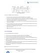
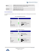
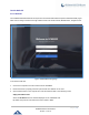
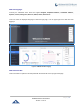
Table Of Contents
- DOCUMENT PURPOSE
- CHANGE LOG
- Firmware Version 1.0.19.27
- Firmware Version 1.0.19.21
- Firmware Version 1.0.18.13
- Firmware Version 1.0.18.12
- Firmware Version 1.0.18.9
- Firmware Version 1.0.17.16
- Firmware Version 1.0.16.20
- Firmware Version 1.0.16.18
- Firmware Version 1.0.15.16
- Firmware Version 1.0.14.24
- Firmware Version 1.0.14.23
- Firmware Version 1.0.14.21
- Firmware Version 1.0.13.14
- Firmware Version 1.0.12.19
- Firmware Version 1.0.11.27
- Firmware Version 1.0.0.7
- WELCOME
- PRODUCT OVERVIEW
- INSTALLATION
- GETTING STARTED
- SYSTEM SETTINGS
- PROVISIONING
- EXTENSIONS
- EXTENSION GROUPS
- ANALOG TRUNKS
- VOIP TRUNKS
- SLA STATION
- CALL ROUTES
- CONFERENCE
- VIDEO CONFERENCE
- IVR
- LANGUAGE SETTINGS FOR VOICE PROMPT
- VOICEMAIL
- RING GROUP
- PAGING AND INTERCOM GROUP
- CALL QUEUE
- PICKUP GROUPS
- MUSIC ON HOLD
- FAX SERVER
- BUSY CAMP-ON
- PRESENCE
- FOLLOW ME
- SPEED DIAL
- DISA
- EMERGENCY
- CALLBACK
- BLF AND EVENT LIST
- DIAL BY NAME
- ACTIVE CALLS AND MONITOR
- CALL FEATURES
- PBX SETTINGS
- SIP SETTINGS
- IAX SETTINGS
- INTERFACE SETTINGS
- API Configuration
- CTI SERVER
- ASTERISK MANAGER INTERFACE (RESTRICTED ACCESS)
- CRM INTEGRATION
- PMS INTEGRATION
- WAKEUP SERVICE
- ANNOUNCEMENTS CENTER
- STATUS AND REPORTING
- USER PORTAL
- MAINTENANCE
- EXPERIENCING THE UCM6200 SERIES IP PBX

P a g e | 40
UCM6200 Series User Manual
Version 1.0.19.27
Figure 4: UCM6204 Back View
To set up the UCM6204, follow the steps below:
1. Connect one end of an RJ-45 Ethernet cable into the WAN port of the UCM6204.
2. Connect the other end of the Ethernet cable into the uplink port of an Ethernet switch/hub.
3. Connect the 12V DC power adapter into the 12V DC power jack on the back of the UCM6204. Insert the
main plug of the power adapter into a surge-protected power outlet.
4. Wait for the UCM6204 to boot up. The LCD in the front will show the device hardware information when
the boot process is done.
5. Once the UCM6204 is successfully connected to network, the LED indicator for WAN in the front will be
in solid green and the LCD shows up the IP address.
6. (Optional) Connect PSTN lines from the wall jack to the FXO ports; connect analog lines (phone and
Fax) to the FXS ports.
7. Note: The ground screw needs to be connected.
Connect The UCM6208
To set up the UCM6208, follow the steps below:
1. Connect one end of an RJ-45 Ethernet cable into the WAN port of the UCM6208.
2. Connect the other end of the Ethernet cable into the uplink port of an Ethernet switch/hub.
3. Connect the 12V DC power adapter into the 12V DC power jack on the back of the UCM6208. Insert the
main plug of the power adapter into a surge-protected power outlet.
4. Wait for the UCM6208 to boot up. The LCD in the front will show the device hardware information when the
boot process is done.
5. Once the UCM6208 is successfully connected to network, the LED indicator for NETWORK in the front will
be in solid green and the LCD shows up the IP address.
6. (Optional) Connect PSTN lines from the wall jack to the FXO ports; connect analog lines (phone and Fax)
to the FXS ports.
Note: The ground screw needs to be connected.