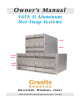
O w n e r ’s M a n u a l S ATA I I A l u m i n u m Hot-Swap Systems 2 BAY 4 BAY 4 BAY Rack 8 BAY Rack Macintosh, Windows, Linux SATA (Serial ATA) Hot-Swap Drive System / Case Kit
Table of Contents Page User Guide How SATA (Serial ATA) Works Connecting SATA Devices 3-4 5 Drive & Host Adapter Installation Removing the Hot-Swap Tray Installing the Drive Installing the Host Adapter Formatting & Partitioning The Drive Troubleshooting 2-4 Bay Hot-Swap Specifics 4-8 Bay Rack Hot-Swap Specifics 2-4-8 Bay Cable Connections Specifications Warranty & Service 6 7-8 9-10 11 12-13 14 15 16 17 18 Granite Digital • 3101 Whipple Rd. • Union City, Ca. 94587 www.granitedigital.
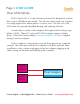
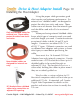
Page 3 USER GUIDE How SATA Works SATA II (Serial ATA) is a High Performance Serial Bus designed to transfer data at up to 300MBytes per second. This ultra-fast data transfer rate is perfect for storage applications where speed is a critical issue. The low cost of the SATA drives also provide affordable backup and archiving solutions. Granite offers a variety of host adapters that support the Hot-Swap capabilities of SATA. These PCI cards and PCMCIA adapters support multiple drives.
USER GUIDE Page 4 How SATA Works In order to get SATA to perform at its maximum speed, the following items should be considered: 1) Pick the controller card that best suits your needs. SATA Host Adapters come in a variety of models from 2 channel to 16 channel RAID cards. Also it is important to note that not all SATA Host Adapters support Hot-Swap and without that ability the drive can only be removed when the computer is turned off. 2) The drive mechanism must go fast.
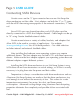
Page 5 USER GUIDE Connecting SATA Devices Granite cases use the “L” type connector because we Hot-Swap the drive mechanism not the cable. Host adapters use both the “L” or “I” types with the eSATA becoming more popular as the external connection, “I” internal. Since SATA uses one channel per drive, each SATA drive must be directly connected to a SATA host adapter channel. Cable length can be up to 72” using Granite shielded external cables.
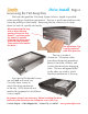
Drive Install Page 6 Removing the Hot-Swap Tray We have designed the Hot-Swap System to be as simple as possible when installing a hard drive mechanism. The tray is easily removed from the frame by pulling on the handle. Removing the tray allows you to swap drives in and out, quickly and easily. When removing the tray with a drive running, gently pull out the tray about 1” and then pause for about 10 seconds allowing the drive mechanism to stop spinning. Then continue to remove the drive.
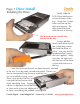
Page 7 Drive Install Installing the Drive Gently slide the SATA Drive Mechanism in from the rear of the tray. Locate the 4 screw holes and line up the drive mechanism. The drive should be flush with the rear of the tray. The drive connectors should face the rear of the tray. Using a phillips head screw driver install the 4 mounting screws that hold the drive in place. Use only the flat headed phillips screws that are supplied.
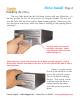
Drive Install Page 8 Installing the Drive The tray slides back into the Hot-Swap System with very little effort. As the tray reaches the last 1/4 inch, push it in using the handle. The tray will now be flush with the front and has been seated properly. Never force the tray into place and always make sure there is nothing in the opening before inserting it. The tray slides on two rails and locks into place. Make sure that both sides are even when sliding it in.
Page 9 Drive & Host Adapter Install Installing the Host Adapter There are two types of PCI Host Adapters on the market and many different variations of these two types. The first type is the PCI-X. As seen in the picture to the right, this PCI bus looks very different than the PCI-E type shown below. Before purchasing a host adapter make sure you know what type of PCI bus your computer has.
Drive & Host Adapter Install Page 10 Installing the Host Adapter Using the proper cable guarantees good data transfers and optimum performance. For external use “shielded cables” are designed to protect the data from static and noise. These cables are much heavier than the internal types and should be used with all of our external systems. Only use shielded cables for When purchasing external shielded cables external use.
Page 11 Drive & Host Adapter Install Formatting & Partitioning After the Host Adapter and drivers have been installed the next step is to format and partition your drive mechanism. This procedure is different in every operating system. The screen on the right is an example of what the Macintosh uses... it is called “Disk Utility”. On a PC running windows it is called “Disk Management”. No matter which operating system you are running the basics are still the same.
Drive & Host Adapter Install Page 12 Troubleshooting 1- THE DRIVE DOESN'T MOUNT: Macintosh OS 9: The Host Adapter manufacturer may have special drivers that will need to be installed with the PCI Host Adapter. Check the manufacturer’s installation instructions for details. Macintosh OS X: When you install a new drive mechanism using OSX, the Application “Disk Utility” is what you use to Partition, Format, RAID, Test, or Erase the drive. Disk Utility is located in the Applications / Utility folder.
Page 13 Drive & Host Adapter Install Troubleshooting 3- THE DRIVE DOES NOT RUN AS FAST AS IT SHOULD: SATA bus speed is determined by four things: 1- The drive performance level. Faster drives (10,000rpm) have higher data transfer rates and make a difference in speed. A larger buffer size also improves drive performance. 2- The Host Adapter technology. SATA Host Adapters come in a variety of speeds and support RAID for even faster performance.
Drive & Host Adapter Install Page 14 2 - 4 Bay Hot-Swap Specifics The 2 & 4 Bay Aluminum Hot-Swap Systems are virtually identical with the exception of 2 extra bays in the 4 bay model. Both models come with an internal Micro ATX power supply with switchable 115 / 230 volt operation. The truly unique feature of these systems is their ability to keep drives running cool without individual fans.
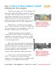
Page 15 Drive & Host Adapter Install 4 - 8 Bay Hot-Swap Rack Specifics The 4 & 4 Bay Aluminum Rack Hot-Swap Systems are virtually identical with the exception of 4 extra bays in the 8 bay model. Both models come with two internal Micro ATX power supplies with switchable 115 / 230 volt operation. The truly unique feature of these systems is their ability to keep drives running cool without individual fans.
Drive & Host Adapter Install Page 16 The rear panel of the 2- 4 Bay SATA System is simple and easy to use. The IEC (standard computer type) power cord plugs into the built in 250 watt Micro ATX power supply. Next to that connector is the power on switch. This switch can be used to power the drive mechansims on or off... or leave this switch in the on position and simply pull the drive mechanisms out about 1” and the drives will disconnect and power down.
Page 17 Specifications DIMENSIONS : 3.5”H x 8.5”W x 12.0”D - 2 - 4 Bay System 3.5”H x 19.0”W x 12.0”D - 4 - 8 Bay Rack POWER SUPPLY : 250W TUV/CE/UL/CSA - 90-264 VAC In. 2-4 Bay System 2 x 250W TUV/CE/UL/CSA - 90-264 VAC In. 4-8 Bay Rack DATA TRANSFER RATE : 300 MB/second (actual speed depends upon the drive and the computer, see page 4 for details) DEVICE SUPPORT : 3.
Page 18 Warranty and Service Granite Digital warrants your SATA Hot-Swap System against any defects in material and workmanship, under normal use, for a period of one year following its date of purchase. In the event this product is found to be defective within the warranty period, Granite Digital will, at its option, repair or replace the defective unit.