O w n e r ’s M a n u a l S ATA I I L C D Hot-Swap Systems EXTERNAL SYSTEM INTERNAL 5.
Table of Contents Page User Guide How SATA (Serial ATA) Works Connecting SATA Devices 3-4 5 Drive Installation Removing the Hot-Swap Tray Installing the Drive Testing the Drive Troubleshooting Setting the Temperature Alarm Internal Hot-Swap Specifics Dual External Hot-Swap Specifics Specifications Warranty & Service 6-7 8-10 11 12-13 14 15 16 17 18 Granite Digital • 3101 Whipple Rd. • Union City, Ca. 94587 www.granitedigital.
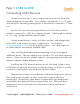
Page 3 USER GUIDE How SATA Works SATA II (Serial ATA) is a High Performance Serial Bus designed to transfer data at up to 300MBytes per second. This ultra-fast data transfer rate is perfect for storage applications where speed is a critical issue. The low cost of the SATA drives also provide affordable backup and archiving solutions. Granite offers a variety of host adapters that support the Hot-Swap capabilities of SATA. These PCI cards and PCMCIA adapters support multiple drives.
USER GUIDE Page 4 How SATA Works In order to get SATA to perform at its maximum speed, the following items should be considered: 1) Pick the controller card that best suits your needs. SATA Host Adapters come in a variety of models from 2 channel to 16 channel RAID cards. Also it is important to note that not all SATA Host Adapters support Hot-Swap and without that ability the drive can only be removed when the computer is turned off. 2) The drive mechanism must go fast.
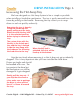
Page 5 USER GUIDE Connecting SATA Devices Granite cases use the “L” type connector because we Hot-Swap the drive mechanism not the cable. Host adapters use both the “L” or “I” types with the eSATA becoming more popular as the external connection, “I” internal. Since SATA uses one channel per drive, each SATA drive must be directly connected to a SATA host adapter channel. Cable length can be up to 72” using Granite shielded external cables.
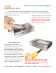
DRIVE INSTALLATION Page 6 Removing the Hot-Swap Tray We have designed our Hot-Swap System to be as simple as possible when installing a hard drive mechanism. The tray is easily removed from the frame by pulling on the handle. Removing the tray allows you to swap drives in and out quickly and easily. Removing the tray is done by lifting the handle up and gently pulling out the tray. Make sure that the key lock is in the unlocked position before trying to remove the tray.
Page 7 DRIVE INSTALLATION Removing the Hot-Swap Tray The Tray should be placed on a flat work surface. When installing the hard drive, static electricity can cause damage to the drive mechanism. Take care to make sure you are grounded properly and are working on a surface that is not prone to static discharge. One way to add a little security is to touch something that has a good ground before touching the drive mechanism.
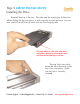
DRIVE INSTALLATION Page 8 Installing the Drive Gently slide the SATA Drive Mechanism in from the rear of the tray. Make sure the wires do not get pinched. Locate the 4 screw holes and line up the drive mechanism. Check to make sure that the wires are inside their channel and not sticking up. Do not pinch them when the drive is secured with the attachment screws. Using a phillips head screw driver install the (4) mounting screws that hold the drive in place.
Page 9 DRIVE INSTALLATION Installing the Drive Reinstall the top of the tray. The side with the notch goes to the front. When sliding the top into place, it will snap into its final position. You are now ready to install the tray back into the Hot-Swap System. The top slides on two rails and locks into place. Make sure that both sides are even when the top is slid on. The top locks into place when the tab at the front of the tray clicks into place. Make sure this tab is securely fastened.
DRIVE INSTALLATION Page 10 Installing the Drive The tray slides back into the Hot-Swap System with very little effort. As the tray reaches the last 1/4 inch, push it in using the handle. The tray will now be flush with the front and has been seated properly. Never force the tray into place and always make sure there is nothing in the opening before inserting it. When the tray is flush with the front it has been inserted correctly. Turn the key lock on to protect the drive from being accidently removed.
Page 11 DRIVE INSTALLATION Testing the Drive Key Lock Green Frame Power LED Green Case Power LED Drive Activity LEDs Without connecting the drive to the computer, plug in the power cable and turn the drive on using the main power switch on the rear of the case. The Green Power LED and Green Frame Power LED should both come on immediately. If the Drive Tray is already inserted, the RED (Drive Inserted) LED should come on and the Blue LCD Display should show both the termperature and the fan speed (RPMs).
DRIVE INSTALLATION Page 12 Troubleshooting 1- THE DRIVE DOESN'T MOUNT: Macintosh OS 9: The Host Adapter manufacturer may have special drivers that will need to be installed with the PCI Host Adapter. Check the manufacturer’s installation instructions for details. Macintosh OS X: When you install a new drive mechanism using OSX the Application “Disk Utility” is what you use to Partition, Format, RAID, Test, or Erase the drive. Disk Utility is located in the Applications / Utility folder.
Page 13 DRIVE INSTALLATION Troubleshooting 3- THE DRIVE DOES NOT RUN AS FAST AS IT SHOULD: SATA bus speed is determined by four things: 1- The drive performance level. Faster drives (10,000rpm) have higher data transfer rates and make a difference in speed. A larger buffer size also improves drive performance. 2- The Host Adapter technology. SATA Host Adapters come in a variety of speeds and support RAID for even faster performance.
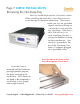
DRIVE INSTALLATION Page 14 Setting the Temperature Alarm The Mode and Set Buttons are used to adjust the alarm. Push the Mode Button for 2 seconds to enter the set mode. There are a total of 4 settings that can be changed. The first is T1 (Temperature 1), then F1 (Fan 1), T2 (Temperature 2), and F2 (Fan 2). Pressing the Mode Button allows you to select any of the 4 settings. When the desired mode has been picked, use the Set Button to adjust its value.
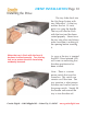
Page 15 DRIVE INSTALLATION Internal Hot-Swap Specifics The Internal SATA Hot-Swap fits into any standard 5.25” opening. It comes complete with the necessary screws to mount it into the computer bay. Power to the SATA Hot-Swap is via a standard 4-Pin Power Connector. The data is supplied using the standard 7 pin SATA connector. Depending on the type of SATA Host Adapter the drives will be either hot-swapable or removable.
DRIVE INSTALLATION Page 16 Dual External Hot-Swap Specifics The External SATA HotSwap System comes complete with everything needed to plug and play except the data cables and host adapter. The enclosure has a built in power supply and plugs into it via a standard IEC computer power cable. In the rear are 2 SATA data connectors that need to be plugged into the optional 3’ or 6’ Shielded SATA cables available for the system.
Page 17 Specifications DIMENSIONS : 2.4”H x 8.25”W x 10.5”D - External System 6.0”H x 7.00”W x 11”D - Dual External System POWER SUPPLY : 50W TUV/CE/UL/CSA - 90-264 VAC In. - External System 80W TUV/CE/UL/CSA - 90-264 VAC In. - Dual External System DATA TRANSFER RATE : 300 MB/second (actual speed depends upon the drive and the computer, see page 4 for details) DEVICE SUPPORT : 3.
Page 18 Warranty and Service Granite Digital warrants your SATAVue Hot-Swap System against any defects in material and workmanship, under normal use, for a period of one year following its date of purchase. In the event this product is found to be defective within the warranty period, Granite Digital will, at its option, repair or replace the defective unit.