RC Recirculating chiller Operating instructions
Recirculating Chiller RC Recirculating chillers RC350G RC400G RC1400G RC3000G Part No 09931/Issue 8 Page 2 August 2001
Recirculating Chiller CONTENTS 1 Safety 4 2 Installation 5 2.1 2.2 2.3 2.4 2.5 2.6 2.7 Connection for closed loop circulation Connection for open loop circulation Siting the chiller Filling the reservoir By-pass Remote alarm socket Remote probe 6 6 7 7 7 8 8 3 Operation 8 3.1 3.2 3.3 3.3.1 3.3.2 3.4 3.5 3.
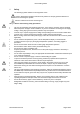
Recirculating Chiller 1 Safety The following symbols marked on the equipment mean:Caution: Read these operating instructions fully before use and pay particular attention to sections containing this symbol Caution: Surfaces can become hot during use. Always observe the following safety precautions • • • • • • • • • • • • • • • • • • • • • Use only as specified by the operating instructions, or the intrinsic protection may be impaired.
Recirculating Chiller 2 Installation Remove packing materials carefully, and keep for future shipment or storage of the unit.
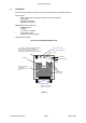
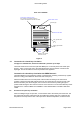
Recirculating Chiller Rear view: RC3000G Power supply voltage connector IEC connector 3 pole fused 10A 250v ~. There are two separate fuses rated 15A 250V Remote alarm socket Overflow pipe Serial number label Inlet pipe 3/8" BSP male th d Outlet pipe 3/8" BSP male Wheels Brakes Brakes on front wheels. Push down to lock. Figure 2 2.1 Connection for closed loop circulation Use pipe of a suitable bore, which will withstand a pressure up to 40psi.
Recirculating Chiller 2.3 Siting the chiller Lift the chiller by the four bottom corners. Take care when lifting as the chillers weigh between 42 and 90 kg when empty. For the most efficient operation, position the chiller so that the air flow through and around it is not restricted. There should be at least 100mm clearance on all sides. Lock the wheels to ensure that the chiller stays in place.
Recirculating Chiller 2.6 Remote Alarm Socket This alarm is operative whenever the liquid temperature goes outside the user-setable bands around the set point. The factory setting for these alarms is 10°C above and below the set point; to alter the setting, refer to section 3.3. During the initial heat up or cool down phase, or whenever the set temperature is changed, the alarm is disabled.
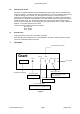
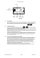
Recirculating Chiller Readout 2132 Heater ‘ ’ alarm Controller OP1 25 OP2 Page button Scroll button Down button Up button Figure 4 3.1 The controller The controller (see Figure 4) is used to set the operating temperature, high and low temperature alarm levels and to initiate the self tune routine. During operation the actual liquid temperature is shown on the display. To view the set point, press and release the ↓ or ↑ button. 3.2 3.
Recirculating Chiller 3.3.1 Setting high alarm offset After setting the required temperature, press the button until the display reads “1dHi”. Press and release ↓the or ↑ button to display the present value of the high alarm. ↓ Press the the or ↑ button again to set the new value for the high alarm. Example: 3.3.2 If the set temperature is 15°C and you want the high alarm to operate if the temperature rises above 20°C , set the high alarm offset to 5°C .
Recirculating Chiller 4.0 Safety devices 4.1 Undertemperature thermostat See section 3.6. There is no alarm for this function. 4.2 Flow fail cut-out If there is no liquid flow everything stops working except the controller, and the alarms operate. When the chiller is first switched on there is no flow. Press the flow fail override switch for 5 seconds to start the flow. The alarms will switch off when the flow starts. 4.3 Overtemperature cut-out This prevents the heater chamber from overheating.
Recirculating Chiller 5 Fault diagnosis Symptom Cause Reason/Recovery procedure No power Check that the chiller is connected to the CORRECT power supply voltage, check all fuses.
Recirculating Chiller 6 Technical specification This equipment is for indoor use and will meet its performance figures within the ambient temperature range 10°C to 35°C, with maximum relative humidity of 80%. Installation category II (transient voltages). Pollution degree 2 in accordance with IEC 664. For operation at altitudes of up to 2000 metres. Conforms to IEC61326-1 (EN 61326-1) Class B except where indicated *.
Recirculating Chiller 7 Maintenance All Grant laboratory products are designed to comply with IEC1010-1 and can be flash tested. Some are fitted with radio frequency interference suppressers. Therefore it is recommended that only a d.c. test is performed. Routine maintenance: Check monthly that dust is removed from the grilles. Check monthly that the line strainer which is fitted on the inlet pipe is clean, particularly when foreign particles can enter the pumped liquid.
Recirculating Chiller 9 Service For service, return for repair to our Service Department or, in other countries, to our distributor. Grant Instruments (Cambridge) Ltd Service Shepreth Cambridgeshire.
Recirculating Chiller Grant Instruments (Cambridge) Ltd. Shepreth, Cambridgeshire, SG8 6GB England Tel: +44 (0) 1763 260811 Fax: +44 (0) 1763 262410 EMAIL: marketing@grantinst.co.uk INTERNET: http://www.grant.co.