Low temperature bath/circulator R series Operating instructions
Version 3 - May 2005 Page 2 Low temperature bath/circulator Operating instructions
Contents 1 2 Safety......................................................................................4 Getting Started.......................................................................6 2.1 2.2 2.3 3 Unit overview Unpacking Installation Operation ...............................................................................8 3.1 3.2 3.3 3.4 3.5 Controls and features Rear panel reference and description Thermostat unit Filling Switching ON and setting up 4 Specific examples.................
1. Safety 1 Safety The following symbols mean:Caution: Read these operating instructions fully before use and pay particular attention to sections containing this symbol. Caution: Surfaces can become hot during use. Always observe the following safety precautions. Use only as specified by the operating instructions, or the intrinsic protection may be impaired. After transport or storage in humid conditions, dry out the unit before connecting it to the supply voltage.
It is the user's responsibility to carry out appropriate decontamination if hazardous material is spilt on or inside the equipment. Do not connect to a power supply or switch on before filling the tank. Take care when topping up or draining, as the liquid in the tank may be very hot or cold. If the alarm lamp is illuminated do not touch the liquid or the tank base, they may be very hot. Refill carefully, a hot heater can cause a spattering of very hot water droplets and scalding steam.
2. Getting started 2.1 Unit overview Optima low temperature circulators provide a source of cooling for many sensitive analytical procedures. Applications requiring the precision temperature control of samples include spectrophotometry, viscometry, refractrometry and electrophoresis.
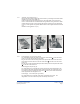
2.3.1 Assembly - All models (see Fig 1) Remove the thermostat mounting plate from the tank by unscrewing the four black knobs located in the corners of the plate (1a). Feed the Optima thermostat through the hole in the bridge plate, being careful not to force it. The thermostat can be located either facing forward or facing to the left. In either position three of the holes in the mounting plate will line up with holes in the thermostat unit (1b).
3. Operation Controls and features (see Fig 2) 3.1 A B C Refrigeration unit power (mains) switch. Over temperature protection re-set. The unit is protected from over heating by the over temperature cut-out. This will be actuated between 110°C and 120°C. To re-set the unit first wait for the liquid to cool below 100°C. Un-screw the black cap, under this is the re-set button, push in to re-set. 5° Switch. With the switch in the position the minimum operating temperature is 5°C.
3.2 1 2 3 4 5 6 7 Rear panel reference and description (see Fig 3) IEC outlet to accessory pump. IEC outlet to Optima Thermostat unit. IEC inlet to Refrigeration unit with integral twin fuse draw. Communications link socket. The refrigeration unit may be controlled with an Optima GR150 or GP200 thermostat unit. This is done by linking the thermostat to the refrigerator with the communications lead supplied. (See specific examples in section 4) Fuse protection for the Communications Lead.
FUSE 250mA(T) 4 5 . FUSE 250mA(T) A A 5 1 4 7 D 7 B B 1 E 1 A A 6 7 7 7 7 6 6 Fig 3f R4L Fig 3e R2L/R3L Fig 3d R1L 3.3 Thermostat unit Allowable temperature range with suitable Refrigeration Units: OPTIMA UNIT Max. temperature ºC Min.
3.4 Filling Before filling the tank, disconnect the mains power supply. Allow for thermal expansion and contraction of the liquid and for any liquid in external circulation paths.
4. Specific examples This section provides the user with specific examples of how the unit may be used to achieve certain requirements. The refrigeration should not be switched (either ON or OFF) more than once during any five minute period. WARNING Before proceeding with a worked example please ensure you have read and understood the rest of this instruction manual. 4.
Equipment: This type of complex thermal ramping requires the use of either a GR150 or a GP200 Optima thermostat. Any of the Refrigeration units can be controlled with the exception of R1/R1L. As this example will reduce the temperature down to -20°C, we can use any of these units. You will also require the Communications lead as supplied with the Refrigeration unit. Liquid: From the section on liquids you will see that the suitable type is 50% water and 50% glycol. 4.2.
Phase 4 Rotate the knob so that [3InsertAfter]is displayed, press S and another segment [4] will be displayed, introducing Phase 4. Rotate the knob so that [4.Temp] is displayed and press S to adjust. Adjust to 40°C then press S to accept. Rotate so that [4Time] is displayed and press the S button to adjust to 20 minutes. As we are still working at elevated temperatures we do not require the refrigeration. Rotate the knob so that [4.Relays] is displayed, by pressing the S button, activate relay [1].
5. Fault diagnosis Symptom Possible cause Action required Unit not switched on Switch on Unit not plugged into power supply Plug in, switch on Fuse blown in unit or in plug (UK units only) Check and replace Electrical power supply failure Check that other electrical appliances on same circuit are working.
Symptom Stirrer motor does not rotate or pump does not operate Version 4 - Jan 2010 Page 16 Possible cause Action required Stirrer obstructed Clear obstruction Pump obstructed Clear obstruction If motor shaft rotates freely, then motor thermal fuse may have blown Have unit checked by competent person Low temperature bath/circulator Operating instructions
6. Technical specification 6.1 Technical Specification This equipment is for indoor use and will meet its performance figures within an ambient temperature range of 10 to 35ºC with maximum relative humidity of 80%. •Installation Category II (Transient voltages). •Pollution degree 2 in accordance with IEC 664. •For operation at altitudes up to 2000 metres.
Version 4 - Jan 2010 Page 18 Low temperature bath/circulator Operating instructions EMC emissions Electrical power max 100 deg C limit H2O freezing protection Ref. Hi.
7. Pump specifications 7.1 Pumps Pumps come as part of the GD120, GR150 and GP200 thermostats. For details on their operation please refer to the appropriate operating instructions (as supplied with the units): GD120………………………..Part No.17090 GR159, GP200………………Part No.17091 If greater head (pressure) is required you can choose from two accessory pumps and the appropriate pump lid. VTP1 (head 10m/flow 9 litres/ min.).............................240V 50Hz VTP2 (head 17m/flow 12 litres/ min.)..................
7.2 Performance graph The graph below shows the shows the pressure and flow performance for the different pumps.
8. Maintenance 8.1. Cleaning The case can be cleaned with a damp cloth after disconnection from the power supply. Do not use solvents. The immersed parts can be cleaned using proprietary heating element cleaners. CAUTION: these may be toxic - follow the cleaner manufacturer's instructions. Before using any decontamination or cleaning method other than recommended, check with our Service Department, or in other countries with our distributor, that the proposed method will not damage the equipment.
9. Guarantee and service 9.1 Guarantee When used in laboratory conditions and according to these operating instructions, this bath is guaranteed for THREE YEARS against faulty materials or workmanship. 9.2 Service All Grant laboratory products are designed to comply with IEC1010-1 and can be flash tested. Some are fitted with radio frequency interference suppressors. Therefore it is recommended that only a dc test is performed. No other routine maintenance is required.
Grant Instruments (Cambridge) Ltd Shepreth Cambridgeshire SG8 6GB England Tel: +44 (0)1763 260811 Fax: +44 (0)1763 262410 www.grant.co.