Grant Aerona Air Source Heat Pump Air to Water Heat Pump Range Installation & User Instructions Tested to BS EN 14511 Part No. DOC.87 Rev.
STOP! Before continuing with the installation of your new Aerona Heat pump, please spend a few minutes confirming the suitability of the Heat Pump to your system. Failure to do so may result in poor performance and wasted time.
Legislation All work that is required regarding the refrigerant circuit must be carried out by an F-gas registered (or equivalent) refrigeration Engineer. On no account should maintenance or repair be carried out on the refrigerant circuit by unqualified personnel. Information regarding the refrigerant used in this Heat Pump. R407c R407C is a mixture of three refrigerants, each of which boil at different temperatures. R407C has a range or glide of approximately 5ºC.
Contents 1 Stop! i Legislation ii Contents 9 Domestic Hot Water 9.1 Temperature Control 26 9.2 Heat Pump Cylinders 26 iii 9.3 Temperature Boost 26 Introduction 1 10 Filling the System 28 1.1 General Information 1 10.1 Filling and Venting - Sealed Systems 1.2 Warranty 1 10.2 Flushing and Corrosion Protection 28 1.3 Important Advice 1 10.3 Antifreeze 28 1.4 Immersion Heater 1 Specifications and Controls 2 11.1 Switching on First Time 29 2.1 Specifications 2 11.
1 Introduction & General Information The Grant Aerona Heat Pump is a low water content – low temperature heat source, designed to be highly efficient when installed and used in line with these installation and user instructions. It is important that these installation instructions are understood and followed to ensure reliable operation in all weather conditions. Failure to do so will result in erratic temperature swings, poor efficiency and an unhappy customer.
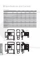
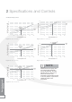
2 Specifications and Controls 2.1 Specifications Model HPAW65 HPAW85 HPAW110 HPAW130 HPAW155 Heating Capacity kW 6.78 8.73 11.32 12.58 15.5 Input Power kW 1.62 2.20 2.61 2.59 2.77 Running Current A 7.36 10.0 11.7 11.8 12.
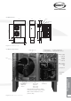
2.2 Dimensions 1120 235 430 Flow 130 Electrical inlet glands 50 555 50 250 788 1470 Return Rear View Front View 90 900 145 400 90 Figure 2-3: HPAW155 model 2.
2 Specifications and Controls 2.4 Heat Pump Curves 16 14 12 10 Water Flow Temperature 35˚C 8 COP 4.1 6 50˚C 4 2 Heat Pump Output in kW Heat Pump Output in kW 16 Water Flow Temperature 35˚C 14 12 10 50˚C 8 6 4 2 0 0 -10 0 10 20 30 40 -10 Air Temperature in ˚C Water Flow Temperature 35˚C 8 COP 3.9 50˚C 6 4 2 0 Heat Pump Output in kW Heat Pump Output in kW 14 10 30 40 14 COP 5.
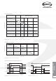
2.5 Pump Curves Wilo-Classic Star 6 Pump Head (metres) 5 Star -RS 15 /6. 4 25 /6 3 2 1 0 0 0.5 1 1.5 Flow (m3/h) 2 3) Figure 2-10: Pump curve for HPAW65, HPAW85, HPAW110 & HPAW130 15.5kW Pump Curve Pump Head (metres) 15 PUN-200E 10 5 0 0 1.2 2.4 Flow (m3/h) 3.6 4.8 Figure 2-11: Pump curve for HPAW155 2.
2 Specifications and Controls 2.7 Controls All Grant Aerona Heat Pumps are supplied with 2 controllers. 1 x heat pump controller (ATC) and 1 x temperature controller (BTC). The ATC is positioned inside the house/building and is normally used in an automatic condition. There are a few parameters that can be adjusted including time and maximum water temperature. The details of these settings can be found in Section 11 of this manual. The BTC is a split temperature controller located inside the heat pump.
3 Siting the Heat Pump 3.1 Position 1. Base The heat pump should be installed on a flat trowelled finished concrete base 150mm thick. This base should extend at least 100mm beyond the unit on three sides. The edge of the concrete base on the side closest to the building should be flush with that face of the heat pump. Refer to Figure 3-1. 300mm To avoid bridging the DPC, leave a gap of at least 300mm between the concrete base and the wall of the house.
3 Siting the Heat Pump 3.2 Orientation The North face of a building will usually have colder ambient air than any other side. To ensure maximum efficiency from the Grant Aerona heat pump, position the unit on a warmer side. In order of preference, site the unit on a South face followed by either South East or South West, then by East or West. Only install on a North face if there is no other alternative.
4 Hydraulic Diagrams The following are examples of suitable systems IMPORTANT 4.1 S-Plan Type - Monovalent The following system diagrams are only concept drawings and not detailed engineering drawings. They are not intended to describe complete systems, nor any particular system. Internal wiring centre Programmer Cylinder Stat It is the responsibility of the system designer, not Grant Engineering UK Ltd.
4 Hydraulic Diagrams IMPORTANT The following system diagrams are only concept drawings and not detailed engineering drawings. They are not intended to describe complete systems, nor any particular system. It is the responsibility of the system designer, not Grant Engineering UK Ltd., to determine the necessary components for and configuration of the particular system being designed including any additional equipment and safety devices to ensure compliance with building and safety code requirements.
4.
4 Hydraulic Diagrams 4.5 Buffers Tanks IMPORTANT When considering the use of a buffer, also consider the space the buffer will take up – it may not be possible to house both a cylinder and a buffer tank. The use of a buffer with the current Aerona heat pump is not necessary in the majority of installations. However, it is possible to utilise a buffer if the end-user wishes to store hot water when there is no other demand placed on the system.
4.
5 System Design Criteria Unlike a typical condensing oil or gas fired boiler that operates at a flow of 70˚C and a return of 50˚C, a heat pump operates with a flow of between 30˚C and 60˚C. The return temperature will depend on the load of the system at a given point in time. The design of any system in the UK is typically based on 2 parameters. 1. That the outside air temperature can fall to as low as -3˚C and that the house comfort temperature will be 21˚C.
6 Calculating Radiator Sizes Existing systems Most existing wet heating systems will use radiators as emitters. When the original system was installed, the radiators would have been sized according to the manufacturer’s specifications. Typically, this would have been 82ºC flow and 71ºC return with the connections being flow at the top and return at the opposite bottom corner.
7 Sealed Systems The following components are required to use the Grant Aerona heat pump as part of a sealed heating system. Due to the lack of space these components are not located within the heat pump, but have to be fitted external to the unit. a) expansion vessel (of the correct size to suit the volume of the system) b) Pressure relief valve – 3 bar c) Pressure gauge d) Filling loop e) Tundish These items may already be installed on the existing system.
8 Electrical IMPORTANT All electrical work must be undertaken by a competent person. failure to observe this legislation could result in an unsafe installation and will invalidate all warranties. 8.1 General The Grant Aerona Heat Pump is very simple to install and to wire. The units are designed to meet the need for simplicity – both in installation and in servicing. As a result, the wiring involved is both minimal and simple compared to other heat pumps available.
Gr Gr Br Br Bl Bl O O Off Off E E L N E 4 5 6 7 8 9 DHW Zone Valve Hlg Zone Valve 8 Electrical 10 Limit 1 Control 2 1 2 Earth connections have been excluded for clarity. Ensure all earth connections are made prior to energising.
8.3 Controller Figure 8-3: ATC connection Figure 8-4: Umbilical cable Figure 8-5: ATC control unit Using the 5m of umbilical cable, connect the controller (right) to the heat pump (left). The controller fits all standard single patresses (surface and flush). Use one of the cable glands at the rear of the heat pump to protect this cable. To extend (if required) simply splice a new section into the middle, ensuring all connections are sound and water proof. The size of cable is 0.
8 Electrical 8.
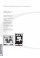
230 Vac Fuse 12 11 10 9 8 7 6 5 4 3 2 1 24 Vac Compressor Heater Compressor 4-way valve N Relay KM2 Expansion Valve Ret Gas Sensor Ext Temp Sensor Low pressure switch High pressure switch Relay KM1 Red Fan motor Blk S Blue R White Orange C 24 23 22 21 20 19 18 17 16 15 14 13 Pump Coil Temp Sensor Dis Gas Sensor Ret Temp Sensor 6kW Electric Element Power Supply Terminal 3 2 1 3 2 1 ATC Controller Socket The 6kW immersion element is ONLY available as a factory fitted option S-Plan Co
8 Electrical 8.
8.
8 Electrical 12 Return sensor 24 11 23 10 22 21 9 8 BTC Supply sensor 230V/24 Vac Transformer Outdoor sensor 7 19 6 18 5 17 4 16 15 3 14 2 13 Fuse 1 Gr Gr Br Br Bl Bl O O Off Off HIg Zone Valve DHW Zone Valve Fuse L N E 4 5 6 7 8 3 2 1 HW CH C Heat pump S-Plan controls connections 9 10 Limit 1 2 Control 1 2 c c 2 L N HW CH MCB Fuse Programmer L 1 3 Room Thermostat Cylinder Thermostat Circulating Pump Compressor Relay 2 in heat pump control pan
8.8 Bivalent Systems 8.9 Extending the Electrics For bivalent systems, it is necessary to disconnect the internal immersion element from the relay inside the heat pump control panel. Taking the live and neutral outputs from this relay extend this wire to the boiler. Isolate this cable through a fused double pole spur switch and mark on the switch that the supply comes from the heat pump. It may be part of the system design to incorporate Solar Thermal into the design.
9 Domestic Hot Water 9.1 Temperature Control The desired hot water temperature stored in the cylinder can be adjusted on the BTC controller. As already mentioned, the heat pump works most efficiently at lower temperatures but these temperatures are not suitable for domestic hot water which should always be stored at about 60ºC. information.
NB. Setting this override switch to OFF does not stop the automatic operation of the immersion element. The required relay, manual override switch and enclosure are available from Grant Engineering UK Ltd as a kit. For details of this Automatic Domestic Hot Water Boost Kit (Grant Ref. HPDHWBK1) refer to Section 15 of these instructions. When fitted, this kit interrupts the electrical supply between the existing immersion heater and the fused immersion switch.
10 Filling the System 10.1 Filling and Venting Sealed Systems ! NOTE For technical details and requirements for Sealed Systems, refer to Section 7 of these instructions. For details of the Grant Sealed System kits for use with the Grant Aerona heat pump range refer to Section 15. IMPORTANT As with all wet heating systems, it is the responsibility of the installer to remove all the air from the heating system after filling. 1.
11 Commissioning 11.1 Switching on First Time When switching on for the first time carry out the following procedures in the order they appear. 1. Ensure the external mains power isolation switch is set to the ‘OFF’ position. 2. Energise the heating system inside the house. 3. Create a CH demand using the timer/programmer. 4. Confirm the CH motorised valve has opened. (You may need to adjust the room thermostat to achieve this). 5.
11 Commissioning 11.2 Setting the ATC Controller Setting the ATC parameters: The main purpose of the ATC controller is to give an overall maximum temperature control over the heat pump. In contrast, the BTC controller will give accurate control over both CH and DHW temperatures, even if they each have different target temperatures. The table shown on page 31 gives a list of the parameters applicable to the ATC. Please note that there are parameters that MUST NOT be altered.
ATC Parameters Parameter 0 1 2 3 4 5 6 7 8 9 A b C d F 10 11 12 13 Description Range Default Comments Return water temperature to start electrical heater Desired Return water temperature setting Defrost cycle Coil temperature point to start defrosting Coil temperature point to stop defrosting Max time for defrosting Reserved Restart after power failure EEV manual / auto control Water pump working mode, 0= Continuous, 1=Normal Fan motor working mode 0= daytime working mode, 1=night time working mode Tar
11 Commissioning 11.3 Setting the BTC Controller To set the BTC controller. 1. Press all 3 buttons for 1 second to enter the mode setting. 2. If ‘Mode1’ is shown, press the button until ‘Mode 3’ is displayed then press ‘Item again. ‘OUTDR START’ should now be displayed. 3. Scroll through the menu using the button, the ‘Item’ button to access the desired function. Use the or button to alter the setting. 4. Press the ‘Item’ button once more to go back to the menu.
BTC Settings Menu Item OUTDR Start Access Active Mode Default Range 1 Always All 21˚C 1 to 29˚C OUTDR DSGN 1 Always All -3˚C -50 to 0˚C BOIL START 1 Always All 21˚C 1 to 65˚C BOIL DSGN 1 Always All 48˚C 21 to 104˚C BOIL MAX 0 Always All 55˚C 48 to 107˚C, OFF BOIL MIN 0 Always All OFF OFF, 26 to 82˚C MASS 0 Always All 1 (lo) 1(lo)<>2(med)<>3(Hi) DIFF 0 Always All AU AU, 1 to 23˚C DHW BOIL TARGET 0 Always All 48˚C OFF, 21 to 104˚C ‘pump’ DLY 0 Alway
11 Commissioning 11.
12 Servicing & Maintenance 12.1 General 12.3 Condensate Disposal Grant Aerona Heat Pumps require only the minimum of routine servicing and maintenance. This basically consists of a visual check of the unit and should be regularly carried out (e.g. annually) to ensure that the heat pump continues to operate in a safe and efficient manner. Check that condensate drain holes in the bottom of the unit are not blocked. 12.
13 Fault Finding 13.
13.
13 Fault Finding it cannot get rid of the heat it is producing. This will be evident if, when switched on from cold or warm, the gauge rises quickly towards the yellow or red zones. If this happens, switch off, and purge the system. (Remember to check the circulating pump is working.) 5. When tracing a fault code, use the table of fault codes on page 32 to help you. As often as not, it will be a wire that has become loose or disconnected.
BTC Temperature ˚C Resistance kW Temperature ˚C Resistance kW Temperature ˚C Resistance kW Temperature ˚C Resistance W -46 490.813 -7 46.218 32 7.334 71 1,689 -43 405.710 -4 39.913 35 6.532 74 1,538 -40 336.606 -1 34.558 38 5.828 77 1,403 -37 280.279 2 29.996 41 5.210 79 1,281 -34 234.196 4 26.099 43 4.665 82 1,172 -32 196.358 7 22.763 46 4.184 85 1,073 -29 165.180 10 19.900 49 3.760 88 983 -26 139.402 13 17.436 52 3.
14 Spare Parts List 12 Vac Transformer Relay PCB Power capacitor BTC 24 Vac Transformer Relay Spare Parts List Figure 14-1: Heat pump control panel components 40 Part Number Description HPAW65 HPAW85 HPAW110 HPAW130 HPAW155 HPAS10 Power capacitor 50µF 1 1 0 0 0 HPAS11 Power Capacitor 60µF 0 0 1 1 0 HPAS12 Power Capacitor 70µF 0 0 0 0 1 HPAS13 Power capacitor 100µF 0 0 1 1 1 HPAS14 Fan Capacitor 4µF 1 0 0 0 0 HPAS15 Fan Capacitor 6µF 0 1 1 1 2 HPAS16
15 Accessories Figure 15-1: Sealed system kit 15.1 Sealed System Kits These are required when the Grant Aerona Heat Pump is used as part of sealed heating system – refer to Section 7 for further details. Kit 1 (Grant Ref.
16 Glossary of Terms Efficiency The word “efficiency” is defined as the ratio of useful heat output to energy input. For example, if we use 1 kW of energy to produce 500W of heat it is deemed to be 50% efficient.
17 Warranty Dear Customer You are now the proud owner of a Grant Aerona Air Source Heat Pump from Grant Engineering (UK) Limited, that has been designed to give years of reliable, trouble free operation. Grant Engineering (UK) Ltd. guarantees the manufacture of the heat pump including all electrical and mechanical components for a period of two years from the date of purchase.
GRANT ENGINEERING (UK) LTD Hopton House, Hopton Industrial Estate, Devizes, Wiltshire. SN10 2EU Telephone: 01380 736920 Fax: 01380 736991 Email: info@grantuk.com Website: www.grantuk.
To be Completed by the Householder Title Initials Surname Address Town County Tel: Home Post code Work Heat Pump Model Mobile Serial Number System Type: Monovalent Bivalent If Bivalent System - other heat source(s): Gas Boiler Oil Boiler Biomass Boiler Other (specify) Heating System (tick all that apply): Radiators only Underfloor only Radiators & Underfloor Hot Water Cylinder Swimming Pool Heater Thermal Store Installer Date installed Address Town County Commissioning Engineer (i
Guarantee Registration Card Grant Air Source Heat Pump Guarantee Air to Water Heat Pump Range • 2 years parts and labour cover on all electrical and mechanical components •Extended warranty available. Contact Grant for details. Important - Don’t Delay! Please complete the attached reply-paid guarantee registration card and return it to: GRANT ENGINEERING (UK) LIMITED Hopton House, Hopton Industrial Estate, Devizes, Wiltshire SN10 2EU Tel: 01380 736920 Fax: 01380 736991 Email: sales@grantuk.com www.