
Installation Kit User guide

NOT FOR USE ON AIRBAG EQUIPPED VEHICLES
CLASSIC/CHALLENGER WHEELS ONLY
IF YOU HAVE A PAINTED SPOKE, YOUR WHEEL CAME WITH A
SILVER FOIL DISC THAT MUST BE USED FOR PROPER HORN
OPERATION. REFER TO INSTRUCTION SHEET WITH WHEEL.
DO NOT THROW AWAY!
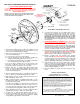
SHOWN: TYPICAL CLASSIC/CHALLENGER INSTALLATION
SEE INSTRUCTION SHEET PROVIDED WITH WHEEL FOR
SIGNATURE SERIES HORN HOOKUP.
1. Point wheels straight ahead and disconnect battery or pull
horn fuse before starting removal of the old wheel so horn
won’t short out and blow during installation.
2. Remove horn mechanism. This is normally done by one or
more of the following steps:
a) Press down on horn cap or ring and turn.
b) Remove emblem cap from its snapped-in condition by
grasping it and pulling toward you, or pry loose.
c) Horn Ring and emblem may be secured by screws which
are concealed in rear side of wheel spokes.
If one of the above operations has not removed all of the
horn parts, it will have exposed the remaining screws to
permit easy removal of the balance of such parts.
3. Remove horn wire or spring loaded metal plunger from
plastic housing by either pulling straight out on the metal
sleeve or, on most models, by twisting the plastic sleeve to
the left and then pulling out..
4. Remove shaft nut retainer clip, if so equipped, and retain for
later use. Remove the shaft nut holding wheel to shaft.
5. Mark shaft as to the top of wheel. (Most shafts have a score
mark denoting this, but be sure).
6. With conventional puller (or GRANT puller 5891), use the
two tapped holes which you will find in the hub of old wheel
to pull off the steering shaft.
If a puller is not available, you may improvise an efficient one
to do the job. By drilling two holes of the proper size in a
short steel bar and using two screws of the proper length
you can tighten them and pull the old wheel very easily.
7. After original wheel has been removed as indicated, place
small tubular metal sleeve down over splined shaft.
8. Position hub on splined shaft observing that “Top A” is
located in accordance with the mark you made in step 5.
You may have to rotate the plastic horn contact tube slightly
to align with the appropriate hole through hub.
FORM #5
On the Web: www.grantproducts.com
9. Insert the wire lead into the new black plastic sleeve,
make sure the small tab on the outside of the sleeve is
pointed toward the bell shaped end of the wire, notice the
bell shaped end will not pass through the sleeve. (The
bell shaped end is inverted from the factory one, but
this is by design). Insert the spring into the plastic tube
first followed by the wire lead/plastic sleeve assembly and
lock into place.
10. TO ENSURE WHEEL IS STRAIGHT;
Route wire around
hub as shown above, from the 10 o’clock position to about
the 2 o’clock position to properly align wheel. Position post
cover and wheel on hub, making sure wire lead passes
through the appropriate holes in the 2 o’clock position.
Using the three shoulder bolts provided, fasten the hub,
post cover and wheel together, but do not tighten.
11. Check wheel for proper position and if correct, reinstall the
shaft nut from Step 4 and tighten. Reinstall the shaft nut
retainer clip. Should retainer not fit into groove on shaft,
tighten nut further until it will fit as originally located.
12. Remove shoulder bolts and reinstall same through
retainer ring with fiber side toward you. When tightening
shoulder bolts please keep in mind that excess torque will
result in damage to the hub. The shaft nut, if properly
tightened, will firmly hold hub/wheel assembly onto shaft.
13. Connect wire lead to connector on retainer ring. Position
spring on center nut (you may find tape a help). Place the
horn cap in position by aligning dimples in cap with reliefs
in fiber material and push until dimples pass fiber. Turn
cap left or right until tight (1/4”-1/2”).
14. Reconnect battery or replace fuse and enjoy your new
wheel.
TORQUE REQUIREMENTS
SHOULDER BOLTS 10-12 FT/LBS
STEERING SHAFT NUT 25-30 FT/LBS
Rev. 4/09 by J.F. 97505-00-01
Our Limited Warranty
We warrant this product for ninety (90) days from the date of original purchase to be
free from defects in materials and workmanship. If, during this period, the product
fails under normal usage because of a manufacturing defect, then we will replace or
repair the item. To obtain repair or replacement under the terms of this warranty,
notify us at 615 Elca Lane, Suite C, Brownsville, TX 78521. Proof of purchase and
date of purchase are required to validate warranty.
All implied warranties, including warranty of merchantability, are limited to this same
ninety-day period from date of original purchase. We are not liable for any direct or
consequential loss or property damage arising from any use of this product. This
warranty gives you specific legal rights, and you may also have other rights which
vary from state to state. Offer good in U.S.A. and Canada only..
IMPORTANT
FOR YOUR OWN SAFETY. DO NOT USE THIS WHEEL FOR ANY COMPETITIVE
OR COMMERCIAL RACING PURPOSES. RACING DOES NOT CONSTITUTE
NORMAL USAGE AND THEREFORE MAKDES THIS WARRANTY VOID.