
Installation Kit User Manual

1. Point wheels straight ahead and disconnect battery or pull
horn fuse before starting removal of the old wheel so horn
won’t short out and blow during installation.
2. Remove horn mechanism. This is normally done by one or
more of the following steps:
a) Press down on horn cap or ring and turn.
b) Remove emblem cap from its snapped-in condition by
grasping it and pulling toward you, or pry loose.
c) Horn Ring and emblem may be secured by screws which
are concealed in rear side of wheel spokes.
If one of the above operations has not removed all of the
horn parts, it will have exposed the remaining screws to
permit easy removal of the balance of such parts.
3. Remove nut which holds wheel to shaft.
4. Mark shaft as to which is the top of the wheel.
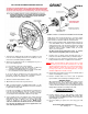
5. With conventional puller (or GRANT puller 5891), use the
two tapped holes which you will find in the hub of old wheel
to pull off the steering shaft.
If a puller is not available, you may improvise an efficient one
to do the job. By drilling two holes of the proper size in a
short steel bar and using two screws of the proper length
you can tighten them and pull the old wheel very easily.
6. If your old wheel has a turn indicator cam, remove this part
and reinstall in the same position on back of custom hub.
Generally this part is affixed to the steering wheel with
screws or clamped on by spring tension. NOTE: Some
cams are molded into the wheel and are not removable,
use roll pin(s) provided in kit for these applications. See
enclosed roll pin instructions.
FORM #4
SHOWN: TYPICAL CLASSIC/CHALLENGER INSTALLATION
Apply grease from enclosed capsules to cover the copper
contact surface on custom hub. This will reduce wear on the
parts and does not interfere with the electrical circuit.
7. When using kit number 3249, install tubular metal sleeve
over shaft. NOTE: Sleeve should fit freely and slide down
until it bottoms. On some models the plastic turn signal
mechanism may prevent it from bottoming or fit snugly
against its sides. If either condition exists, do not use
sleeve, it is not required.
(A) Note Ford special instruction notice on reverse
side of this form regarding stub on end of shaft.
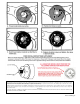
8. Position hub on splined shaft observing that ”top” is
located in accordance with the mark you made in Step 4.
9. Position post cover and wheel using the three shoulder
bolts provided in kit, but do not tighten them at this time.
NOTE:
When using kit 3294 on older Fords. If there is a gap
between the post cover and the column, there is an easy
adjustment that must be made. Loosen the bolts under the
dash holding the column in position, move the column
housing up or down as needed leaving about a 1/8” gap
and then retighten these bolts securely.
10. Check wheel for position and, if correct, install the wheel
retainer nut and tighten securely.
11. Remove shoulder bolts. See reverse side for pictorial
representation of the remaining assembly procedures.
GENERAL NOTES
When tightening the three shoulder bolts, please keep in
mind that excessive torque will result in damage to the
hub as well as possibly cause the contact plate to fracture
or distort. The wheel retainer nut, if properly tightened, will
firmly hold the hub/wheel assembly to the shaft.
TORQUE REQUIREMENTS
SHOULDER BOLTS 10-12 FT/LBS
STEERING SHAFT NUT 25-30 FT/LBS
12. Position spring on nut, you may find tape a help. Place
horn cap in position by aligning dimples with reliefs in fiber
material and push until dimples pass fiber. Turn cap left or
right until tight (1/4”-1/2”).
13. Reconnect battery or replace fuse and enjoy your new
wheel.
On the Web; www.grantproducts.com
Rev. 4/09 by J.F. 97504-00-01