FLEXmax Series Charge Controllers (FLEXmax 80, FLEXmax 60) Owner’s Manual
About OutBack Power Technologies OutBack Power Technologies is a leader in advanced energy conversion technology. Our products include true sine wave inverter/chargers, maximum power point tracking charge controllers, and system communication components, as well as circuit breakers, batteries, accessories, and assembled systems. Contact Information Address: Corporate Headquarters 17825 – 59th Avenue N.E.
Table of Contents Introduction ................................................................................................................................................................. 5 Features .................................................................................................................................................................................................... 5 Firmware ....................................................................................................
Table of Contents Changing the Settings on the FLEXmax ...................................................................................................................................... 24 Accessing the Main Menu ........................................................................................................................................................... 24 Main Menu Map...........................................................................................................................
Table of Contents Summary Screens ................................................................................................................................................................................ 71 Status Screens ....................................................................................................................................................................................... 72 MODE Screens ...................................................................................
Table of Contents List of Tables Table 1 Table 2 Table 3 Table 4 Table 5 Table 6 Table 7 4 Battery Voltage and Charge Timer............................................................................................................................. 21 Aux Mode Functions....................................................................................................................................................... 27 Regulatory Specifications for All Models ...........................................
Introduction IMPORTANT: This manual provides safety guidelines and installation information for the FLEXmax Series Charge Controllers. It does not provide information about specific brands of PV modules and supplies limited information on batteries. Contact the supplier or manufacturer of the PV modules or batteries for additional information. Thank you for purchasing a FLEXmax Series Charge Controller (CC).
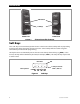
Introduction LCD Screen Soft Keys FLEXmax 80 Figure 1 FLEXmax 60 Charge Controller Features Soft Keys Four “soft” keys are located directly below the LCD. The functions of the soft keys will vary depending on the location of the user within the menu structure. Some soft keys will be used for navigation. Some soft keys will be used for programming. Soft key functions are identified by text in the LCD screen directly above the key (e.g., EXIT).
Installation Standards and Requirements All installations must comply with national and local electrical codes; professional installation is recommended. IMPORTANT: The charge controller is designed for indoor installation or installation inside a weatherproof enclosure. It must not be exposed to rain and should be installed out of direct sunlight.
Installation Dimensions 16.25” (41.3 cm) FLEXmax 80 Charge Controller 5.75” (14.6 cm) FLEXmax 60 Charge Controller Figure 3 8 4.0” (10.2 cm) 13.5” (34.
Installation Mounting the Charge Controller IMPORTANT: Install the FLEXmax in an upright position out of direct sunlight. The FLEXmax is designed to attach directly to OutBack’s FLEXware 500 DC and FLEXware 1000 DC enclosures (FLEXware 500 shown) or attach to its own charge controller brackets (FW-CCB, FW-CCB2, and FW-CCB2T). Mounting directly to a FLEXware DC enclosure: 1. Remove the fan cover and bottom cover from the FLEXmax. 2.
Installation Wiring This section provides instructions on installing PV array wiring into the FLEXmax controller. See page 98 for more notes on PV array sizing and operation. Wire and Disconnect Sizing IMPORTANT: Wire sizes must comply with local and national codes. Input conductors and circuit breakers must be rated at 1.56 times the short-circuit current of the PV array (per NEC). OutBack 100% duty continuous circuit breakers only need to be rated at 1.25 times the short-circuit current.
Installation Wiring Compartment WARNING: Shock Hazard Make sure all DC circuit breakers are OFF (open) BEFORE making any wiring connections. Use a DVM to check for voltage on all wires. The PV (-) and BAT (-) terminals are connected internally. Only one negative wire may be needed to connect to the (-) wire lugs if the PV - and BAT- conductors are bonded at the negative bus bar. See Figure 6, Figure 7, and Figure 8 for sample wiring diagrams.
Installation Figure 6 12 Wiring Diagram - Single Charge Controller with PV Array 900-0009-01-00 Rev C
Installation Figure 7 900-0009-01-00 Rev C Wiring Diagram – Charge Controller with PV Array and Inverter 13
Installation Figure 8 14 Wiring Diagram – Charge Controller with PV Array Ground Fault Protection 900-0009-01-00 Rev C
Operation Operation of this unit consists of monitoring screens and programming screens. The majority of programming screens are accessed using the main menu. See page 24. Power Up Screens IMPORTANT: The default settings of the FLEXmax are for a 12 Vdc battery bank. Change the setting after powering up if a different battery voltage is used. Once set, the FLEXmax retains the nominal voltage setting. Following any type of shutdown or disconnect, it will return to operation automatically.
Operation Version and/or Voltage Setting Screens Once the password has been entered, the display will return to the Select Version screen. Select Version Screen To change the version: Select Version Elija la Version English NEXT ENTER ENTRA SEL 1. or Select Version Screen Select Version Elija la Version English NEXT ENTER ENTRA SEL Press or to cycle through the version choices of: English, Australian, or Espanola. 2.
Operation Status Screen The status screen displays system information. See page 18 for detailed information of the different modes of operation. The optional OutBack system display shows CC (Charge Controller) status screens for convenient distant viewing from the installation location. See page 59 for the FLEXmax screens displayed on the MATE3. Please see pages 71 to 83 to view the FLEXmax screens displayed on the MATE (or MATE2). Status Screen In Out 11.6V 13.8V 0.000 kW AUX: OFF 0.0 A 0.0 A 0.
Operation End-of-Day Summary Screen The end-of-day summary screen appears after one hour of continuous Sleeping (see page 23). This screen can be opened any time by pressing the second soft key while in the status screen, providing a summary up to that point. End-of-Day Screen NOTE: When finished viewing the end-of-day screen(s), be sure to return the display to the status screen. Otherwise, it will not reset the counters when the sun rises the next morning. The values will continue to accumulate.
Operation Navigating the End-of-Day Screens and Data Logging Status Screen In Out 11.6V 13.8V 0.000 kW AUX: OFF End-of-Day Screen 0.0 A 0.0 A 0.0 kWH Sleeping Today 000Ah 00.0kWH 011Vp 00.0Ap 0.00kWp MAX 14.7 V ABS 01:00 MIN 14.6 V FLT 00:00 Press SK1 to return to the status screen. Pressing the second soft key (SK2) opens the end-of-day summary menu/logging. CLEAR LOG Screen The daily statistics or the accumulated statistics are stored on the charge controller's static memory.
Operation Modes of Operation The FLEXmax has 25 different modes that will display on the status screen. These messages will vary with function. The FLEXmax modes consist of various charging stages, equalization, various reasons for stopping charging, and certain specialized operating modes. The amount of time required before starting operation is dependent on the module type, ambient temperature, and the amount of sunlight directly on the PV array.
Operation Table 1 Battery Voltage and Charge Timer Battery Voltage ChgT (Charge Timer) Activity/Display 12.4 V, 24.8 V, 37.2 V, 49.6 V, or 62.0 V, and less than the Absorbing voltage No change. <12.4 V, 24.8 V, 37.2 V, 49.6 V, or 62.0 V For every minute elapsed, 1 minute is subtracted from the timer <12.0 V, 24.0 V, 36.0 V, 48.0 V, or 60.0 V For every minute elapsed, 2 minutes is subtracted from the timer < 11.6 V, 23.2 V, 34.8 V, 46.6 V, or 58.
Operation EX-Absorb There is an external DC source other than PV keeping the battery above the Absorbing voltage set point. The FLEXmax will stop charging because it is not needed. Floating The FLEXmax is in the Float stage of a three-stage cycle, regulating the battery voltage at the Float voltage set point. This stage is temperature compensated. (See page 97.) If the battery voltage drops below the Float voltage, the FLEXmax will employ the MPPT function to draw more power from the PV array.
Operation MPPT EQ The equalization cycle has started and the charge controller is trying to regulate the batteries at the BATTERY EQUALIZE VOLTS set point. Once this voltage has been reached, the displayed mode will change to EQ. Before equalizing, battery loads should be turned off and the battery should be charged so the charge controller can quickly reach the EQ voltage set point. Otherwise, the charge controller may have difficulty reaching or maintaining the equalization process.
Operation Unloaded The battery terminals have become disconnected. This may mean that the battery circuit breaker breaker has tripped. It can also appear if the nominal battery voltage is set too low. Wakeup As the PV open circuit voltage (Voc) rises above the battery system voltage by two volts, the FLEXmax prepares to deliver power to the batteries, although it does not perform MPPT in this mode.
Operation Main Menu Map Main Menu From the main menu, a user can choose among the following FLEXmax functions by aligning the arrow next to the desired selection. Charger Aux Light EQ Misc Advanced Logging Stats EXIT GO returns to the Status screen. <> moves the cursor to the left. <> moves the cursor to the right. goes to the setup screen for the chosen option.
Operation Charger Screen Charging settings should follow the battery manufacturer's recommendations. This screen allows changes to the recharging voltage set points if the default settings do not match the manufacturer's recommendations. (For an explanation of battery charging, see pages 96 and 97). Current Limit Absorbing Float The default charger output current limit setting is: 80 amps for the FM80, and 60 amps for the FM60. This setting is adjustable from 5-80 amps.
Operation Aux Screens The AUX (Auxiliary) is a secondary control circuit — essentially, a small power supply that provides a 12 Vdc output current (up to 200 milliamps/2.4 watts) to an isolated load. It is either ON (Active High) with 12 Vdc available at the output or OFF (Active Low) with 0 Vdc at the output. It can also be set to AUTO, so that it activates when certain criteria are met.
Operation Table 2 Mode Name Error Output Aux Mode Functions Function/Purpose Function: When the voltage decreases below the threshold voltage for 10 minutes or more, the AUX output will change state. Set Points Aux Polarity Threshold Voltage Not Available Threshold voltage Active High: Activates for a set amount of time when the voltage drops below the threshold for a set amount of time. Purpose: This mode is useful for monitoring remote sites.
Operation Table 2 Mode Name Aux Mode Functions Function/Purpose Set Points Function: Low Battery Disconnect When the battery voltage falls below the threshold disconnect voltage, the AUX output activates. When the battery voltage rises above the threshold reconnect voltage, the AUX deactivates. Purpose: Threshold Voltage for disconnect Aux Polarity Not Available Threshold voltage for reconnect Time delay This mode is intended to operate a relay to turn off loads and save battery capacity.
Operation Vent Fan (AUX Mode) This mode is intended to operate a vent fan for a battery enclosure which helps ventilate hydrogen gas from the enclosure. If the voltage remains above the threshold voltage set point, the vent fan will remain active. When the voltage falls back below the set point, the vent fan will continue for another 15 seconds, then turn off.
Operation PV Trigger (AUX Mode) This mode is intended to operate an alarm, or relay that disconnects the PV array, when PV input exceeds the threshold voltage set by the user. The mode turns off the alarm or PV disconnect after the PV voltage decreases below the threshold for a time period that is set by the user. CAUTION: Hazard to Equipment Do not exceed 150 Vdc or the FLEXmax could be damaged. To set the mode for PV Trigger: Main Menu Charger Aux Light EQ Misc Advanced Logging Stats EXIT GO 1.
Operation Error Output (AUX Mode) This mode is useful for monitoring remote sites. It is intended to signal when the charge controller has not charged the batteries for 26 hours or more or if the battery voltage has fallen below the threshold voltage for more than 10 minutes. The 26-hour timer can be viewed. When set as Active Low, it can operate an alarm by sending a signal through a modem to a computer to alert the operator of the condition.
Operation Night Light (AUX Mode) This mode is intended to operate a user-provided, low wattage light for as long as the charge controller remains in Sleep mode or for the ON time set by the user. OFF is the default value. Main Menu To set the mode for Night Light: Charger Aux Light EQ Misc Advanced Logging Stats EXIT GO Charger Aux Light EQ Misc Advanced Logging Stats EXIT GO 1. From the main menu, press <> or <> to move the to the left of the Aux function. 2.
Operation Float (AUX Mode) This mode is intended to operate a load when the FLEXmax is in the Float stage of charging the batteries. Main Menu Charger Aux Light EQ Misc Advanced Logging Stats EXIT GO To set the mode for Float: 1. From the main menu, press <> or <> to move the to the left of Aux. 2. Press to open the AUX MODE screen. 3. Press until Float is displayed in the AUX MODE screen. 4. Press to cycle through the mode set points ON, OFF, or AUTO.
Operation Diversion (AUX Mode) When external DC sources (wind, hydroelectric) are directly connected to a battery bank, any excess power should be sent to a diversion load, such as a heating element, using a mechanical relay or solid-state relay. In Diversion mode, the user programs set points — from -5.0 volts to 5.0 volts relative to the Absorbing, Float, and EQ voltages — to activate the AUX output.
Operation ...continued from previous page. AUX MODE Diversion:Relay Output: Off EXIT NEXT SET To change the set points for Diversion:Relay: Off MODE 1. Press to advance to the set point screens; and
Operation Diversion:Solid St (AUX Mode) Main Menu IMPORTANT: Charger Aux Light EQ Misc Advanced Logging Stats EXIT GO Charger Aux Light EQ Misc Advanced Logging Stats EXIT GO AUX MODE Diversion:Solid St Output: Off Off EXIT NEXT SET MODE proceeds to the next AUX MODE screen. If using wind or hydroelectric turbines, keep the charge controller’s diversion voltage slightly above its Absorb and Float voltage settings for efficient functioning.
Operation Continued from previous page… To change the set points for Diversion:Solid St: AUX MODE Diversion:Solid St Output: Off Off EXIT NEXT SET MODE 1. Press to advance to the set point screens; and
Operation Figure 27 900-0009-01-00 Rev C Wiring Diagram for Diversion Load and AUX Wiring 39
Operation Low Battery Disconnect (AUX Mode) This mode disconnects “auxiliary” loads from the batteries in the event of low voltage. These are separate from the usual loads. Auxiliary loads are controlled by the AUX output, usually by a larger relay. When the battery voltage falls below the DISCONNECT VOLTS setting, the AUX loads are disconnected. When the voltage rises above the RE-CONNECT VOLTS, they will be reconnected.
Operation Remote (AUX Mode) Remote allows an OutBack system display to control the charge controller's auxiliary output. Some displays may require a certain level of software in order to use this feature. Consult the owner's manual for the system display being used for details. Main Menu To set the mode for Remote: Charger Aux Light EQ Misc Advanced Logging Stats EXIT GO 1. 2. 3. 4.
Operation EQ – Battery Equalize Equalization is a controlled overcharge that is part of regular battery maintenance. Equalization brings the batteries to a much higher voltage than usual and “simmers” them for a period of time. This has the result of removing inert compounds from the battery plates and reducing stratification in the electrolyte. Equalization follows the same pattern as standard three-stage charging.
Operation Automatic Equalization Mode To enable an automatic equalization mode, an interval must be set for the number of days to pass between equalization cycles. This interval can be between 1 to 250 days. The default equalization interval setting is 000 which disables this feature. The Equalization Interval screen allows the user to set the interval between equalization cycles. It also displays how many days of the interval has passed.
Operation Misc Screen There are three Misc screens that provide technical information about the operating state of the system. These are read-only screens and allow for no changes to any of the settings. They do provide the means to wake up the charge controller if it is in Snooze mode. They also provide a means to force the charger into a Bulk or Float stage. Main Menu Charger Aux Light EQ Misc Advanced Logging Stats EXIT GO To access the Misc screens: 1.
Operation Misc Screen #1 GT STATE 255 07 EXIT PWM% 50.0 NEXT To bring the charge controller out of Snoozing mode: ChgT 005 RSTRT 1. Press . 2. Press to return to the main menu. Misc Screen #1 GT STATE 255 07 EXIT PWM% 50.0 NEXT To force the charger into a Bulk or Float charge cycle: ChgT 005 Force Bulk/Float Screen EXIT 1. Press . 2. Select either a Float or Bulk charge cycle. Forcing a Float or Bulk recharge will end an EQ cycle.
Operation Advanced Menu The Advanced menu allows fine-tuning of the FLEXmax operations including Snooze periods and Maximum Power Point limits (see page 95). The following modes are available in the Advanced menu. They will appear in the following order.
Operation Wakeup Mode (Advanced Menu) Wakeup Mode sets the open-circuit voltage (Voc) conditions that cause the charge controller to wake up during Sleep and Snooze modes. Since environmental conditions impact the open-circuit voltage of an array, the Voc can be based on the last measured Voc value. Before changing these values, monitor the system for a week or so using the factory defaults and then gradually adjust the set points.
Operation GT allows the FLEXmax to work more effectively with a grid-interactive OutBack inverter. This setting automatically raises the charge controller’s Float voltage to equal its Absorption voltage. Since the inverter sells power to maintain its own Float, Absorption, or Sell settings (all of which should be lower than those of the controller), this mode makes it easier for the inverter to sell power. (See pages 44 and 102 for more information on this mode.
Operation Absorb Time Limits (Advanced Menu) The amount of time the charge controller stays in the Absorbing stage of charging can be adjusted in the Absorb Time Limits screen. An Absorbing charge stage normally ends when the battery voltage is maintained at the Absorbing set point for the time period set in the Absorb Time Limits screen. Absorb Time is adjustable from 0 to 24 hours (consult the battery manufacturer’s recommendations).
Operation Rebulk Voltage (Advanced Menu) In the Float stage, if the battery voltage falls below the ReBulk Voltage set point for at least 90 seconds, the FLEXmax will automatically initiate a new charge cycle. To adjust the set points in the Rebulk Voltage screen: Rebulk Voltage 1. ADVANCED MENU Rebulk Voltage 12.0V EXIT NEXT + Navigate to the Rebulk Voltage screen through the ADVANCED MENU as instructed in Figure 35. 2.
Operation For example: During cold weather, a battery often requires a higher charging voltage. Some inverters might not accommodate these higher voltages and can shut down during charging, cutting off power to their loads. During hot weather, limiting the RTS Compensation values assures the voltage stays high enough to charge the batteries instead of dropping too low in reaction to a higher ambient temperature.
Operation Auto ReStart (Advanced Menu) This setting allows the user to choose between continuous maximum power point (MPP) tracking, or occasional restarts of the sweeping process. A restart means the controller abandons the existing maximum power point value it was using and “re-sweeps”, or begins gathering new power point data. (See page 95 for more information on MPP tracking.) Auto ReStart has three options available: Mode 0 – Initial sweep only and then continuous MPP tracking.
Operation Aux Polarity (Advanced Menu) When the AUX function is ON, 12 volts DC is present at the AUX terminals (Active High). When the AUX function is OFF, 0 volts DC are present at the terminals (Active Low). Aux Polarity allows the user to reverse the availability of this voltage for the Night Light, PV Trigger, or Diversion Relay functions. When one of the these functions has been chosen as the AUX function, an arrow in the right hand corner of the screen will reflect the Aux Polarity state.
Operation Logging The Logging screen in the main menu enables the user to clear the daily and cumulative logs if necessary. Logs can be downloaded to an SD card if a MATE3 is installed. See page 69 for details. The FLEXmax daily log begins when the controller enters Wakeup. See page 24. IMPORTANT: If two or more charge controllers are used in the same system and are started up or cleared on different days, their numeric dates will not be the same.
Operation Stats The STATS screen in the main menu displays additional voltage and time information. In a stand-alone FLEXmax controller — one that is not connected to a system display — Sunrise shows how long ago the FLEXmax woke up for the first time each day and when the daily and total logged values were updated and cleared. If the FLEXmax is connected to a system display, the logging occurs at midnight.
Operation The Secondary Stats screen shows the total accumulated DC and AC kilowatt-hours and kiloamp-hours of the charge controller. Secondary STATS Screen Total Total BACK Total Total BACK 00000 0000.0 kWH kAH Pressing the soft key switches the screen between DC kilowatt-hours and AC kilowatt-hours. DCkWH 00000 0000.0 kWHAC kAH DCkWH shows the DC kilowatt-hours and should be used in a system that is not grid-interactive. ACkWH is used with a grid-interactive system.
Operation Rebooting the FLEXmax If the screen becomes garbled or the FLEXmax controller otherwise will not respond to commands, it may be necessary to reboot its internal processor. IMPORTANT: Rebooting the FLEXmax controller will return all the values and set points to the factory defaults. These values are listed on page 94. It is advisable to record all custom values before rebooting. To reboot the FLEXmax: 1. Turn off the battery and PV array circuit breakers.
Operation NOTES: 58 900-0009-01-00 Rev C
MATE3 System Display and Controller The MATE3 provides the means for programming the FLEXmax charge controller and other devices when preprogrammed default settings do not work for the destined installation.
MATE3 Screens Charge Controller Soft Key PV Icon Charge Controller Soft Key Press this soft key to view FLEXmax charge controller status information. If no charge controller is present, the PV icon will be blank and this soft key will be inoperative. Charge Controller’s Mode Charge Controller Modes: Bulk Absorb Float EQ Silent The FLEXmax has over 25 modes. The MATE3 can only display five status messages and may substitute one of the five for a FLEXmax mode not on this list.
MATE3 Screens DataLog Screen The soft key shows accumulated daily amp-hour and watt-hour statistics, as well as maximum current, wattage, and maximum and minimum voltage figures. These maintain a continuous daily log, up to 128 days, which can be recalled. One day can be displayed at a time. See page 55 for more information. Current Date Screen Items: The upper left corner shows the date of the selected Datalog screen. (The current Datalog screen reads "Today.
MATE3 Screens Graph Screens The soft key brings up the following screens which plot various type of data over time. The first screen shows changes in PV wattage over time. This axis shows date and time in 6-hour increments. This axis shows PV wattage. Figure 57 Output Graph The soft key brings up a screen showing changes in battery voltage over time. This axis shows date and time in 6-hour increments. This axis shows battery voltage.
MATE3 Screens Menu Structure in the MATE3 Figure 60 shows the MATE3 menu structure for adjusting the FLEXmax charge controller settings. Figure 60 Menu Structure The Main Menu shown above is accessed with the LOCK button and a password. Use the MATE3’s control wheel to move up and down between menus (or options within a menu). Use the center button on the control wheel to make a selection. (See the MATE3 manual for more information.
MATE3 Screens Charge Controller Settings Charge Controller menu options include the following: Charger ------------------------------------------------------------- > MPPT ---------------------------------------------------------------- > Temperature Compensation ------------------------------- > Battery Equalize ------------------------------------------------ > Grid-Tie Mode --------------------------------------------------- > Auxiliary Output ------------------------------------------------ > Restart M
MATE3 Screens Temperature Compensation When equipped with the Remote Temperature Sensor (RTS), the charge controller compensates for temperature changes by raising or lowering its charging voltages. However, in some cases the sensitivity of other DC devices may require this temperature compensation to be limited. This menu allows the user to manually adjust the upper and lower limits of temperature compensation. See page 97 for an explanation of compensation.
MATE3 Screens Auxiliary Output (Charge Controller) This menu controls the output and functionality of the Auxiliary (AUX) output. The charge controller’s AUX terminals provide a 12 Vdc output that can deliver up to 0.2 Adc to control external loads. Typical loads include signaling a generator to start, sending a fault alarm signal, or running a fan to cool the inverter. See page 11 for an image of the AUX terminals. See page 27 for a description of AUX modes.
MATE3 Screens Night Light Set Points : Active: High or Low. Threshold Hysteresis Time ON Time Figure 70 Night Light Float Set Points : None Figure 71 Float Diversion: Relay and Solid St Set Points (NOTE: All items function identically for both Diversion: Relay and Diversion: Solid St, except for Active: High or Low): Figure 72 Active: High or Low.
MATE3 Screens Calibrate The Calibrate menu allows adjustment of the charge controller’s battery voltmeter. If a particular controller’s readings do not match those of another device, or a hand-held meter, the calibration feature may improve consistency.
MATE3 Screens Device Data Logs Users of the MATE3 can create Device Data Logs for the FLEXmax charge controller. The Data Logs can then be uploaded and saved to an SD card. Saving Data Logs for the FLEXmax Charge Controller To create a data log for the FLEXmax Charge Controller: 1. Access the Main Menu as shown in Figure 16. 2. Select the Device Data Logs menu. 3. Select FLEXmax Charge Controller menu. 4. Select Upload and Save Data Log on the FM Charge Controller Data Log menu. 5.
MATE3 Screens Data Log File Format Information generated by this function will be saved on the SD card in a generic .csv file format, which can be read by most spreadsheet programs. Data Logging example: NOTE: This header line is NOT included in the download. Date AH Kwh Max Amps Max Watts Absorb Time Float Time Min Battery V Max Battery V MAX VOC 6/13/11 0 0 1.2 29 0:00 0:00 24.1 29.1 122 6/12/11 38 0.9 5.5 143 0:00 0:00 24.1 29 122 6/11/11 32 0.8 5.
MATE/MATE2 Screens Summary Screens If a FLEXnet DC is installed in the system, the following summary screens will be available. FLEXnet DC Summary Screen #1 FLEXnet DC Summary Screen #2 FLEXnet DC Summary Screen #3 FLEXnet DC Summary Screen #4 FX Inverter/Charger Summary Screen (If the FNDC is not installed, this will be the 1st Summary Screen.
MATE/MATE2 Screens Status Screens To view the status screens of a FLEXmax 60 or FLEXmax 80 using a MATE, follow the illustration below. Changes to FLEXmax settings can only be changed from the charge controller user interface; changes can not be done when viewing these screens on a MATE. MODE Screens MAIN-----------------1:35:04p Navigation for STATUS/CC/MODE SUM returns to the STATUS/CC/PAGE1 screen. moves to the next menu item in the diagram.
MATE/MATE2 Screens METER Screens MAIN-----------------1:35:04p Navigation for STATUS/CC/METER SUM returns to the CC/PAGE1 screen. moves to the next menu item in the diagram. moves to the previous menu item in the diagram. returns to the first CC/METER screen for the port shown. directs the MATE to read the next device (port) on the HUB.
MATE/MATE2 Screens SETPT Screens Navigation for STATUS/CC/SETPT MAIN-----------------1:35:04p returns to the CC/PAGE1 screen. SUM moves to the next menu item in the diagram. moves to the previous menu item in the diagram. returns to the first CC/SETPT screen for the port shown. directs the MATE to read the next device (port) on the HUB.
MATE/MATE2 Screens LOG Screens MAIN-----------------1:35:04p Navigation for STATUS/CC/LOGS SUM returns to the CC/PG2 screen. moves to the next menu item in the diagram. moves to the previous menu item in the diagram. returns to the 1st CC/LOG1 screen for the port shown. directs the MATE to read the next device (port) on the HUB. displays log information from one day earlier. Logs can be displayed from as far as 128 days in the past.
MATE/MATE2 Screens STAT Screens MAIN-----------------1:35:04p SUM STATUS SETUP ADV STATUS---------------choose device FX CC DC returns to the CC/PAGE2 screen. moves to the next menu item in the diagram. moves to the previous menu item in the diagram. returns to the CC/STAT/PAGE2 screen for the port shown, with the exception of the “end of the cc stats” menu. From the “end” menu, the soft key returns to the 1st CC/STAT screen.
MATE/MATE2 Screens Advanced Menus The Advanced menus available in the MATE or MATE2 system display allow the following options: Change the settings of the FLEXmax battery charger and temperature compensation Change the parameters of the FLEXmax MPPT process Change the settings of the FLEXmax equalization process Calibrate the FLEXmax meters Change the settings of the Auxiliary output to run small AC or DC loads Start a generator using Advanced Generator Start (AGS) Mode (see page 41)
MATE/MATE2 Screens CHGR Menu Navigation for ADV/CC/CHGR moves to the next menu item in the diagram. increases the value of the selection. decreases the value of the selection. directs the MATE to read the next device (port) on the HUB. returns to the CC/PAGE1 screen. returns to the CC/CHGR screen. exits the Advanced menus and returns to the main menu (see page 77).
MATE/MATE2 Screens CC ADVANCED Menu CC/Advanced The ADVANCED screens adjust the same settings that are available on the Advanced screen in the FLEXmax (see page 46). These settings relate to charging, MPPT, temperature compensation, and calibration. Navigation for ADV/CC/ADVANCED Figure 88 900-0009-01-00 Rev C moves to the next menu item in the diagram. increases the value of the selection. decreases the value of the selection.
MATE/MATE2 Screens EQ Menu Navigation for ADV/CC/EQ moves to the next menu item in the diagram. increases the value of the selection. decreases the value of the selection. directs the MATE to read the next device (port) on the HUB. returns to the CC/EQ screen. returns to the choose device screen. exits the Advanced menus and returns to the main menu (see page 77).
MATE/MATE2 Screens AUX Menu Navigation for ADV/CC/AUX moves to the next menu item in the diagram. increases the value of the selection. decreases the value of the selection. directs the MATE to read the next device (port) on the HUB. returns to the CC/PAGE2 screen. returns to the choose device screen. exits the Advanced menus and returns to the main menu (see page 77).
MATE/MATE2 Screens MATE and MATE2 Menu Maps for the FLEXmax STATUS Menu Map Navigation for STATUS/CC/PAGE1 moves to the next menu item in the diagram. returns to the previous menu item in the diagram. directs the MATE to read the next device (port) on the HUB. returns to the STATUS/CC/PAGE1 screen. returns to the screen at the top of the respective column.
MATE/MATE2 Screens Navigation for STATUS/CC/PAGE2 moves to the next menu item in the diagram. returns to the previous menu item in the diagram. directs the MATE to read the next device (port) on the HUB. returns to the STATUS/CC/PAGE2 screen. returns to the screen at the top of the respective column.
MATE/MATE2 Screens Advanced Menu Map Navigation for ADV/CC/PAGE1 moves to the next menu item in the diagram. returns to the previous menu item in the diagram. directs the MATE to read the next device (port) on the HUB. returns to the CC/PAGE1 screen. returnsto the choose device screen.
MATE/MATE2 Screens Navigation for ADV/CC/PAGE2 moves to the next menu item in the diagram. returns to the previous menu item in the diagram. directs the MATE to read the next device (port) on the HUB. returns to the CC/PAGE2 screen. returns to the choose device screen.
MATE/MATE2 Screens This page intentionally left blank.
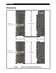
Menu Maps for the FLEXmax Figure 95 900-0009-01-00 Rev C FLEXmax Startup Screens 87
FLEXmax Menu Maps Figure 96 88 FLEXmax Menu Map (Page 1) 900-0009-01-00 Rev C
FLEXmax Menu Maps Figure 97 900-0009-01-00 Rev C FLEXmax Menu Map (Page 2) 89
FLEXmax Menu Maps Figure 98 90 FLEXmax Menu Map (Page 3) 900-0009-01-00 Rev C
Troubleshooting IMPORTANT: Be sure to check out the OutBack customer and user forum at www.outbackpower.com/forum/ for more FLEXmax information. Symptom FLEXmax does not boot/power-up (blank LCD) Remedy Check the battery connection and polarity. Reverse polarity or an improper connection will cause power-up issues. Check the battery disconnect or circuit breaker. Ensure all circuit breakers are sized appropriately. Check the battery voltage at the FLEXmax terminals. A battery voltage below 10.
Troubleshooting Symptom FLEXmax is always SLEEPING Remedy Check battery voltage. If the battery voltage is at or above the Absorbing voltage set point (compensated for battery temperature), the FLEXmax will not wake up. Check PV voltage. The PV voltage has to be at least two volts greater than the battery voltage for the initial wakeup. If voltage is not present, check the PV array breaker (or fuse). Confirm the PV array breaker (or fuse) is sized appropriately.
Specifications Electrical and Mechanical Specifications Specification FLEXmax 60 FLEXmax 80 Output Current Rating @ 40°C ambient 60 amps continuous 80 amps continuous Nominal Battery System Voltage 12, 24, 36, 48 or 60 Vdc (adjustable) PV open circuit voltage 150 Vdc maximum (ETL Rating for UL1741 Standard); 145 Vdc temperature corrected Voc (operational maximum) Standby power consumption Less than 1 watt typical Charge cycle Three-stage Voltage regulation set points 13-80 Vdc Temperature co
Specifications Default Settings and Ranges Table 4 Mode Menu Item Current Limit (FLEXmax 80) Current Limit (FLEXmax 60) Default 60 Adc Range: 5 to 60 Adc Absorbing Float Vent Fan Volts PV Trigger Hold Time Sec PV VOLTS ERROR OUTPUT ERROR LOW BAT VOLTS Night Light ON Hysteresis Time (Minutes) On Time (Hours) Threshold Voltage Float Diversion:Relay Hold Time (Seconds) Delay Time (Seconds) Absorb-Float-EQ Relative Volts HYST Diversion:Solid St Hold Time (Seconds) Delay Time (Seconds) Absorb-Float-EQ Relat
Applications Maximum Power Point Tracking Maximum Power Point Tracking (MPPT) is the technology used by FLEXmax controllers to optimize the harvest of power from PV arrays. PV modules do not have a defined operating voltage. Their voltage is defined strictly by the load connected to them. With no load (disconnected), a module displays “open-circuit” voltage (Voc), and delivers no current. At full load (shorted), a module has no voltage, although it delivers the maximum “short-circuit” current (Isc).
Applications Three-Stage Battery Charging The FLEXmax charge controller is a sophisticated, multi-stage battery charger that uses several regulation stages to allow fast recharging of the battery system while ensuring a long battery life. This process can be used with both sealed and non-sealed batteries. The FLEXmax is a “buck” converter which turns higher PV voltages into the lower charging voltages used by batteries (with correspondingly higher currents).
Applications ABSORBING This is the second stage of charging. It is a constant-voltage stage. Current varies as needed to maintain the Absorbing voltage setting. However, it will typically decrease to a very low number over time. This “tops off the tank”, leaving the batteries at essentially 100% of capacity. The duration of the Absorbing stage is the user-defined Absorb Time Limit. The ChgT timer is preset to zero following the previous charge cycle.
Applications Array Design Sizing Guidelines Below is a list of maximum array wattages for the FLEXmax for various nominal voltage batteries. This should be used for sizing an array. Note that every PV module is different. The specifications for every model should be consulted before designing or assembling a PV array.
Applications Maximum-Power Voltage (Vmp) Maximum-power voltage (Vmp) is the operating voltage for the PV array at which the array generates the most wattage. When designing the PV array, it is recommended for the Vmp to be approximately 12 to 24 volts higher than the nominal battery voltage for optimum performance. This will ensure that the Vmp is always above the battery voltage, which is required for charging. Higher voltages are not recommended, as they may reduce the FLEXmax conversion efficiency.
Applications Hydroelectric and Fuel Cell Applications Performance Optimization The FLEXmax Charge Controller is designed to work with PV arrays. Although it will work with hydroelectric turbines and fuel cells, OutBack Power Technologies can only offer limited technical support for these applications due to variance in turbine and fuel cell specifications.
Applications Main Menu Charger Aux Light EQ Misc Advanced Logging Stats EXIT GO To adjust the Lower Mpp Range Limit: 1. From the main menu, press <> to move the arrow next to the Advanced function. Charger Aux Light EQ Misc Advanced Logging Stats EXIT GO 2. Press . ADVANCED MENU Snooze Mode < 0.6 amp EXIT NEXT AMP 3. In the ADVANCED MENU screen, press again to display the Mpp Range Limit % Voc screen. 4. Press <1/2> until FULL appears. 5.
Applications Grid-Interactive Settings When using an OutBack inverter, FLEXmax, HUB, and system display, set the FLEXmax to GT in the Advanced menu. GT mode allows the inverter to manage the FLEXmax Float setting. It ensures the FLEXmax always keeps the battery above the sell voltage of the inverter. (See page 48.) When using a FLEXmax charge controller with an inverter without the use of a HUB, GT mode will not work because the FLEXmax cannot communicate with the inverter.
Applications Definitions The following is a list of initials, terms, and definitions used with this product.
Applications THIS PAGE INTENTIONALLY LEFT BLANK.
Index A Absorb End Amps .......................................................................... 49 Absorb Time Limits ....................................................................... 49 Absorbing .................................................................................. 20, 97 Advanced Menu ............................................................................. 46 Absorb End Amps ................................................................... 49 Absorb Time Limits................
Applications L Language ................................................................................... 15, 16 Logging ........................................................................ 19, 54, 69, 75 M Main Menu ................................................................................ 15, 24 MATE or MATE2 Advanced Menus .................................................................... 77 AUX .............................................................................81 CC ADV.......
Applications Three-Stage Battery Charging .................................................. 96 Timers Float (reading) .......................................................................... 61 Troubleshooting ............................................................................ 91 U U-Pick ................................................................................................. 47 V Vbatt Calibration .....................................................................50, 68 Vmp .......
Applications THIS PAGE INTENTIONALLY LEFT BLANK.
Applications THIS PAGE INTENTIONALLY LEFT BLANK.
Corporate Headquarters 17825 – 59th Avenue N.E. Suite B Arlington, WA 98223 USA +1.360.435.6030 900-0009-01-00 Rev C European Office Hansastrasse 8 D-91126 Schwabach, Germany +49.9122.79889.