
Installation Guide


MATE3 Screens
60 900-0009-01-00 Rev C
Charge Controller Soft Key
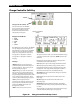
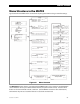
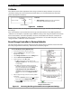
Figure 55 Charge Controller Soft Key Screens
Charge Controller Soft Key
Press this soft key to view FLEXmax
charge controller status information.
If no charge controller is present,
the PV icon will be blank and this
soft key will be inoperative.
Charge Controller Modes:
Bulk
Absorb
Float
EQ
Silent
T
he FLEXmax has over 25 modes. The MATE3
can only display five status messages and
may substitute one of the five for a FLEXmax
mode not on this list. Check the FLEXmax
status screen to determine its exact mode.
See page 20 for a description of modes.
See page 96 for a description of battery
charging.
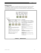
Soft Keys:
<Datalog> brings up a group of charge
controller statistics that are maintained as a
continuous daily log. These screens are all
shown beginning on page 61.
<Graph> brings up a series of screens that
plot various charge controller information
over time. The graphs include inverter and
charger wattage, power imported from an AC
source, battery voltage, and others. These
screens are all shown beginning on page 62.
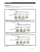
<Port> cycles through each device
connected to the network. If more than one
charge controller is installed in the system,
pressing the <Port> soft key will cycle
through each controller.
<Back> returns to the previous screen.
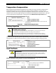
Screen Items:
T
he upper left corner of the screen shows the FLEXmax charge
controller’s current mode of operation.
Bulk
is shown in this
illustration.
In displays the present PV array operating voltage and the
current being harvested from the array.
VOC displays the open-circuit voltage available from the PV.
Out displays the present battery voltage and the current
being delivered from the charge controller(s) to charge the
battery bank. To the right, this line displays the number of
kilowatt-hours and amp-hours accumulated that day.
Operating displays the total hours the charger has operated
that day in any stage.
Float displays the run time of the Float timer when in the
Float stage.
A
bsorb displays the run time of the timer when in the
Absorbing stage.
Maximum displays the maximum amperage and wattage
harvested from the PV array that day, and the time both were
recorded.
The lower right corner shows the current status of the charge
controller’s Auxiliary (AUX) output. (See page 66.)
PV Icon
Charge Controller’s
Mode