
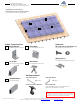
Instructions / Assembly

Subject to technical changes Copyright © 2012 HatiCon Solar, LLC ∙ 2821 E. Philadelphia Street, Suite A, Ontario, CA 91761 USA Page | 2
∙ Telephone: 1-909-235-7150 ∙ Fax: 1-909-235-7151 ∙ Email: info@HatiConSolar.com ∙ Website: www.HatiConSolar.com
Installation Instructions:
Pitched Roof Mounting System
*for framed PV-Modules in portrait mode
Slide the Mid Clamp up to
the module. Slide the next
module up to the Mid-Clamp
and tighten the clamp by
turning the bolt clockwise.
Torque: 7 ft-lbs (9 N-m)
Continue the same process
with the rest of the modules in
the row.
7 ft-lbs
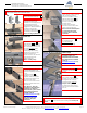
Step 2: Mounting rail to Angle Bracket
Step 1: Flashing/Standoff and L-bracket
Haticon Solar’s pitched roof systems must be attached to an approved and properly
installed standoff or flashing system of the installer’s choice.
Step 4: Module Installation, End Clamps
Place the first module onto the
rails and hold in place by
method of installer’s choice.
Slide the End Clamp onto
the end of the mounting rail
and up to the edge of the
module frame.
An End Clamp must be
attached at each end of the
rail on every module row.
Note: Rows must be interrupted
every 40 feet with an End-
Clamp to allow for thermal
expansion.
Tighten the End Clamp
by turning the bolt
counterclockwise.
Torque: 7 ft-lbs (9 N-m)
Mfg. required torque
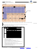
Step 5: Module Installation, Mid-Clamps
D
D
D
7 ft-lbs
Note: For the optional WEEB
grounding system, see
Installation Instructions: WEEB
Grounding System, available
online at
www.haticonsolar.com or by
request.
Step 6: Module Installation, End Clamps
E
Step 3: Connecting Rails
Continue fastening all the rails
to the Angle Brackets until
system is completely attached
to roof.
A 13/60 Rail Splice is
required to connect rails
together. Slide the rail splice
into the first rail until the rivet
head stops the splice.
Slide the second rail over the
rail splice until the rivet head
stops the rail.
Note: Allow a ½ inch gap
between the rails for thermal
expansion. For details on
thermal breaks, please refer to
Thermal Break Instructions,
available online at
www.haticonsolar.com or by
request.
Note: No through bolt is
required for the splice
connection.
Install approved flashing or
standoff devices for the
installation of mounting rails. It is
recommended that the
standoff/flashing devices be
staggered for better distribution
of weight over the joists.
Fasten the Angle Bracket to
the flashing or standoff device.
Torque: Per mfg. requirements
A
Once all the modules in the row are installed, place an
End Clamp on the end of each mounting rail. See step 4 for
details.
D
Rivet head
7 ft-lbs
Attach the 13/60 Rail to the
Angle Bracket . Insert the T-
bolt on the Angle-Bracket into
the C-channel on the rail. Turn
the T-bolt clockwise until it
stops(approx. ¼ turn.)
Properly align the T-bolt by
ensuring the groove on the
bottom of the T-bolt is
perpendicular to the direction
of the rail (see picture).
Tighten T-bolt nut.
Torque: 7 ft-lbs (9 N-m)
B
A
C
Attach the Mid Clamp by
clicking it onto the rail as
shown.
E
Insert T-bolt into Angle Bracket
and loosely fasten with nut.
A
½” thermal gap
Slide on
CLICK
T-bolt groove direction
Rail direction