
Instructions / Assembly


www.grapesolar.com
Tel. 1-877-264-1014 (toll free), 1-541-349-9000, Fax: 1-541-343-9000
3
QuickStart Setup
Valid from June 2018
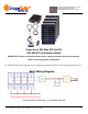
GS-400-KIT PHOTOVOLTAIC POWER GENER-
ATION SYSTEM
CONFIGURATION MANUAL Rev. 180601
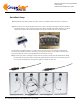
Step 4: Use the 5-foot 10 awg red & black cable pair to connect your positive and negative battery terminals to
the “Battery Positive” (use red cable from the positive battery terminal) and “Battery Negative” (use black
cable from the negative battery terminal) inputs of the charge controller (the center set of terminals).
Step 3: Mount the controller if desired (note that it must be in a NEMA-4 rated enclosure if it is outdoors).
If your battery has sufficient charge (11.5 volts or more), the LCD screen on the controller should activate.
This means the controller has power (controllers are powered by the battery, not the panels). This does NOT
mean that the batteries are full—typically full batteries read around 13.6 volts.
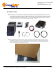
Step 6: Connect the positive and negative outputs of the four panels to the inputs of the parallel cables, adding
the inline fuses on the positive leads. Note that the parallel cables have two shorter center leads for the cen-
ter two panels, and longer leads on the left and right for the panels on either side.