TopTile Mounting System SunModo PV Rack Mounting System UL2703 Compliant Pub.
TopTile Mounting System Please read carefully before installing Product is tested to and recognized to UL 2703 standards for safety grounding and bonding equipment and meets UL 1703 fire standards. SunModo PV Rack Mount System can be used to mount photovoltaic (PV) panels in a wide variety of locations. All installations shall be in accordance with NEC requirements in the USA. The self-bonding system is for use with PV modules that have a maximum series fuse rating of 30A.
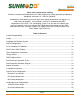
TopTile Mounting System Mid Clamp Attachment ............................................................................................................ 25 Ground Wire Attachment ............................................................................................................ 26 Ground Lug Installation............................................................................................................ 26 Rail End Covers .....................................................................
TopTile Mounting System Installer Responsibility: Before ordering and installing materials, all system layout dimensions should be confirmed by field measurements. SunModo reserves the right to alter, without notice, any details, proposals or plans. Any inquiries that you may have concerning installation of the photovoltaic (PV) system should be directed to your SunModo Sales representative. Consult SunModo Sales for any information not contained in this manual.
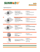
TopTile Mounting System SunModo Self-Bonding System SunModo developed a proprietary grounding and bonding system that is built into the mounting hardware for the rails, clamps and splices. We provide further grounding through all of the SunBeam racking components including the Pipe Caps, Beams, Posts and Post Base Plates. All hardware meet UL 2703 Grounding and Fire Standards tested by ETL.
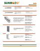
TopTile Mounting System TopTile Components: Rafter Kit includes: 1X Rafter Stanchion 1X 3/8 Hex Flange Screw 1X AL Flashing with EPDM Sealant Cover K10206-005 5” Rafter Mounting System K10206-007 7” Rafter Mounting System Wood Deck Kit includes: 1X Tripod Stanchion 3X #14 Wood Screws 1X 3/8 Hex Flange Screw 1X AL Flashing with EPDM Sealant Cover K10207-105 5” Wood Deck Mounting System Concrete Deck Kit includes: K10206-005 1X Stanchion 1X 3/8 Hex Flange Screw 1X AL Flashing with EPDM Sealant Cover 1
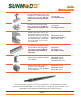
TopTile Mounting System #14 X 5” Wood Screw Used on 5” tall Tripod Stanchions and with 1” Spacer B15058-005 #14 X 5” Wood Screws #14 X 7” Wood Screw Used on 7” tall Tripod Stanchions and with 1” Spacer B15058-007 #14 X 7” Wood Screws Helio Rails: Features both 1/4” and 3/8” side slots, and 1/4” top slot for clamping PV panels. Available in 124”, 166” and 206” lengths. Last 3 digits denote rail length. 4 stock sizes in clear and black.
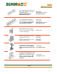
TopTile Mounting System 3/8” Slot Rail Splice Kit with 2X 3/816 hex bolts and flange nuts with integral grounding. May be repositioned until torqued to final value. K10178-001 HR250/HR350 3/8” Splice For single-use only 1/4” Slot Rail Splice Kit with 4X bolts and flange nuts with integral grounding. May be repositioned until torqued to final value. K10177-001 K10177-BK1 HR250/HR350 1/4” Splice For single-use only End Clamp Kit, fits panel height from 31 to 50 mm.
TopTile Mounting System Grounding Mid Clamp Kit with shared rail adaptor for standard rail; fits panel height from 31 to 50 mm. May be repositioned until torqued to final value. K10182-XXX For single-use only Grounding Lug Kit with Grounding Spacer and 1/4-20 T-Bolt. May be repositioned until torqued to final value. K10179-001 For single-use only HR150 (Open Rail): Features wire management channel and both 1/4” and 3/8” side slots, and 1/4” top slot for clamping PV panels.
TopTile Mounting System List of Compliant PV Modules UL 2703 Qualified Modules for use with SunModo PV Racking Systems Evaluated PV Modules Module manufacturer Model numbers Boviet Solar BVM6610M-250, BVM6610M-255, BVM6610M-260, BVM6610M-265, BVM6610M270, BVM6610M-275, BVM6610M-280, BVM6612M-325, BVM6612M-330, BVM6612M-335, BVM6612M-340, BVM6612M-345, BVM6612M-350, BVM6610P250, BVM6610P-255, BVM6610P-260, BVM6610P-265, BVM6610P-270, BVM6612P310, BVM6612P-315, BVM6612P-320, BVM6612P-325, BVM6612P-330 C-S
TopTile Mounting System Kyocera KD315GX-LFB, KU260-6MCA, KU265-6MCA, KD255GX-LFB2, KD260GX-LFB2, LG LG275S1C-G4, LG280S1C-G4, LG285S1C-G4, LG300N1C-G4, LG300N1K-G4, LG300N1T-G4, LG305N1C-G4, LG305N1K-G4, LG310N1C-G4, LG310N1K-G4, LG310N1T-G4, LG315N1C-G4, LG320N1C-G4, LG335S2W-G4, LG340S2W-G4, LG360N2W-B3, LG365N2W-B3, LG365N2W-G4, LG370N2W-G4, LG375N2W-G4, LG380N2W-G4, LG385N2W-G4, LG390N2W-A5, LG395N2W-A5, LG400N2W-A5 Mitsubishi PV-MLE270HD, PV-MLE275HD, PV-MLE280HD Panasonic VBHN285J40 Phono Sola
TopTile Mounting System SolarWorld (V2.
TopTile Mounting System Fault Current Path Diagram Items are listed in the fault current path in order from the PV Panel to the Grounding Lug: 1. 2. 3. 4.
TopTile Mounting System Tools Required for Installation: Electric Drill or impact driver. Note that the use of an impact driver is strongly discouraged for all stainless nut and bolt hardware.
TopTile Mounting System Torque Wrench 3/8” drive, 0 to 35 ft. lbs. Anti-seize compound (Permatex 80071 or equivalent).
TopTile Mounting System Torque Values: These values must be adhered to for mechanical strength. It is required that a torque wrench be used to measure the bolt torque during final assembly, and it is recommended that anti-seize compound, such as Permatex, be applied to the screw threads. Hardware Torque #14 Wood Screws As required 1/4-20 Bolts and Hex Flange Nut 7.5 ft. lbs. 1/4-20 Ground Lug, Flange Nut with 7/16 Hex Head 7.5 ft. lbs. 1/4-20 Ground Lug, Setscrew with 1/8 Allen drive. 4.2 ft. lbs.
TopTile Mounting System TopTile Mount Series: SunModo offers 3 choices of TopTile Mounts for rafter mounting, wood deck mounting and concrete deck mounting. The TopTile Mounts provide a strong, low-profile roof attachment solution for flat or curved tiles. Another important feature of the TopTile Mounting System is the hand formable Flashing along with its EPDM Cover which provides superior leak protection. TopTile Mount Options: Rafter Mounting System: Available Stanchion heights: 5” and 7”.
TopTile Mounting System Deck Stanchion Selection Diagram: 1. CORRECT tripod hole position: Tripod holes are above the tile and below the collar of the EPDM Cover. Note: Repositioning the Tripod Stanchion higher or lower along the tile will increase or decrease the position of the tripod holes. Correct 2. Acceptable tripod hole position: Tripod holes are above the tile, yet above the collar of the EPDM Cover. Addition Great Stuff FireBlock spray foam can be used to prevent water infiltration.
TopTile Mounting System Spacer Assembly: 19 of 27
TopTile Mounting System Installation Instructions: Step 1: Drill 1. Locate and mark the desired location of the TopTile Mount. 2. Using a hand drill guide and a 1-1/2” tile hole saw, drill a hole into the tile. 3. If installing the Rafter Mounting System: Drill 5/32" pilot hole into the rafter in accordance with the NDS guidelines. It is important that the pilot hole is centered about the hole in the tile. 1 Step 2: Clean 4. Remove tile dust from around the hole in the tile and underlayment.
TopTile Mounting System Step 5: Wood Screws 9. Install the three Wood Screws into the Stanchion. 10. Note: Due to the side driving force of installing the screw into the side of the Stanchion, care should be taken to keep the Stanchion plum. Step 6: Flashing (Materials not provided) 11. Apply a bead of structural sealant, ChemLink M1 or equivalent, in the shape of an upside down U on the backside of the flashing and install flashing over Stanchion and under the edge of the tile located above. 5 12.
TopTile Mounting System Portrait Panel Configuration: With a full range of components the TopTile Mounting System can be configured in an endless variety of designs. The system is UL 1703 compliant for Class-A Fire Rated for Type 1 and 2 PV Modules and UL 2703 compliant for electrical bonding tested by ETL. Proceed with the mounting of the PV panels using the Mid and End Clamps. Specific mounting instructions are shown in the following sections for portrait mounting.
TopTile Mounting System Minimum Panel Height Minimum leading edge height to meet a UL1703 PV module fire standard is 3 inches. 3 inch minimum from bottom of PV module frame to the roof covering End Clamp Attachment There must be a minimum of 1.5 inches of Rail extending beyond the PV panel frame. Clamp the PV panel frame by inserting the T-Bolt into the Rail slot. Position the End Clamp firmly against the PV panel frame and secure using the 1/4-20 Collar Bolt. Using a 7/16” socket, torque to 7.5 ft. lbs.
TopTile Mounting System Landscape Panel Configuration: The TopTile Mount System conveniently accommodates landscape configurations to minimize roof time and parts required. The system is tested by IAPMO, UL 1703 compliant for Class-A Fire Rated for Type 1 and 2 PV Modules and UL 2703 compliant for electrical bonding tested by ETL. Proceed with the mounting of the PV panels using the Mid and End Clamps. Specific mounting instructions are shown in the following section for landscape mounting.
TopTile Mounting System Minimum Panel Height Minimum leading edge height to meet a UL1703 PV module fire standard is 3 inches. 3 inch minimum from bottom of PV module frame to the roof covering End Clamp Attachment End Clamps are used at the ends of a row of PV panels. Insert the T-Bolt in the Rail slot and turn clockwise 90° to engage the head into the slot. Insert Grounding T-Bolt Holder to lock T-Bolt in place. Thread the 1/4” Collar Bolt onto the top of the TBolt as shown.
TopTile Mounting System Ground Wire Attachment The picture shows a grounding lug mounted on one Rail per row of panels, and a #6 solid copper grounding wire connecting the Ground Lugs to the building ground per NEC 690.47. Ground Lug Installation One Rail per row of panels should have a Ground Lug for fastening the ground conductor to the array. The Ground Lug is mounted on the top or side of the Rail using a special 1/4” TBolt, Grounding Spacer, and Flange Nut.
TopTile Mounting System UL 2703 Label Placement When requested the UL 2703 Label can be located on East-West running Rail or Beam. See www.sunmodo.com for current warranty documents and information.