
User Manual


3. The Specification
When turning on or adjusting the radio control system it is essential to keep transmitter
antenna at least 30 cm away from receiver antenna all the time. If transmitter antenna is
too close to receiver antenna, receiver will be overloaded and the red status LED on
receiver blinks red. Transmitter responds by repeating a single beep every second and the
radio control system is entered Fail-Safe mode. If the distance of the antennas between
transmitter and receiver would be simply longer than 30cm in this situation, the beep of
transmitter is ceased and the red status LED on the receiver turns off
4. LED indicator
You may check the signal reception according to status LED
• LED off : Very good reception
• LED blinking : Poor reception
• LED on : No signal reception
OPERATION
1. Binding
• GR-12L
Turn on receiver‟s power and press Bind button on receiver for 3 seconds, the red status LED turns off.
Follow the procedures of your specific transmitter to bind, the system will connect within a few seconds.
NOTICE: Once transmitter and receiver are connected, the red status LED on the receiver is off, indicating
the receiver is bound to the transmitter. If the binding process has failed, repeat the whole
procedure.
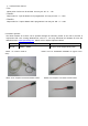
• Binding a number of receivers in one model
It is possible to bind a number of receivers to a transmitter in one model. Every receiver must be bound
to the transmitter individually according to the procedure already described. The last bound receiver is
the master receiver when the system is in use. Every telemetry sensors installed in the model must be
connected to the master receiver, since the only master receiver transmits the sensor data through the
downlink channel. The second and all further receivers are operated as the slave mode which are
connected in parallel to the master with the downlink channel switched off. The control signals can be
passed to a number of receivers simultaneously and also the different signal can be assigned to each
receiver through the channel mapping function of the transmitter or the optional TELEMETRY BOX. The
typical example would be the use of two servos for each aileron, etc.
Parameter Spec
Channel 6
Frequencies 2.400 – 2.483.5 GHz
Modulation FHSS spread spectrum
Input Voltage 3.6 ~ 8.4V
Display Indicator One LED(red)
Upgradable Firmware Yes(CH5)
SUMD Signal Yes(CH6)
Fail Safe Hold/Fail safe
Ch mapping Yes