
User's Manual


by “jittering” or “growling”.
HoTT sum signal (SUMD): if you activate the digital sum signal at channel 6, a sum signal containing
eight channels is present at this socket, instead of a servo signal. The HoTT receiver congured as
SUMD constantly generates a digital sum signal from 8 control signals from the transmitter and makes
this signal available at the appropriate servo socket, which is receiver-specic. At the time these
instructions were revised, this type of signal is used by several of the latest electronic developments in
the area of ybarless systems, heavy-duty airborne power supplies, etc.
WARNING: if you wish to use this facility, it is essential to observe the set-up information supplied with
the devices connected to the receiver, otherwise there is a risk that your model may be uncontrollable.
Channel 5 (Ch5): channel output 5 can be used to control a servo, as a telemetry socket or for voltage
monitoring. If you activate voltage monitoring, the receiver can measure a voltage of up to max. 25.5
V DC via this input (instead of a servo or telemetry sensor) using the circuit described in section 3.1.
The monitored voltage is then displayed on the screen instead of the receiver voltage. This makes it
possible, for example, to monitor the ight battery directly, without the need for an additional voltage
sensor.
If channel 5 is set to ‘sensor’ or ‘voltage’ instead of servo, the channel 5 signal is automatically
available at channel 6. This change will not take effect until turning on / off the receiver.
3.3 FREE MIXERS
Important note: If you wish to use the gyros,
you must always set the tail type to ‘normal’ in the
transmitter’s model type menu. If your model is a delta,
features a V-tail, or has two elevator servos, you must use the
receiver mixer - not the transmitter mixer - to control these
control surfaces, since the gyro stabilisation system will
have no effect on these servos otherwise. The four receiver
mixers work ‘downstream’ of the gyros. If you have already
programmed mixer functions in the “Wing mixers” or “Free
mixers” menu of your HoTT transmitter, you must ensure that
those mixers do not overlap with those available in this menu!
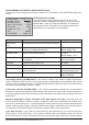
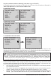
Screen Display Key Settings
MIXER Mixer select 1, 2....4
FROM CHANNEL Signal source / source channel 0,1,2,...6
TO CHANNEL Target channel 0,1,2,...6
TRIM Trim position in % -15 - + 15%
TRAVEL- Travel limit at % Servo travel -150 bis +150%
TRAVEL+ Travel limit at % Servo travel -150 bis +150%
MIXER: up to four mixers can be programmed simultaneously. You can switch between Mixer 1, Mixer
2, … and mixer 4 in the “Mixer” line.
The following settings only affect the mixer selected in this line.
FROM CHANNEL: the signal present at the signal source (or source channel) is mixed in to the target
channel (TO CHANNEL) to an extent which can be set by the user. The method of setting up the values
is analogous to the “Free mixers” menu in HoTT transmitters.
TO CHANNEL: part of the source channel signal (FROM CHANNEL) is mixed into the target channel
(TO CHANNEL). The mixer ratio is determined by the percentage values entered in the “TRAVEL-“ and
“TRAVEL+” lines. Select “0” if you do not require the mixer.
8
Manual Receiver GR-12+ 3xG Graupner HoTT 2. 4
RX FREE MIXER < >
>MIXER:
MASTER CH:
SLAVE CH:
>TRIM:
>TRAVEL-:
TRAVEL+:
1
1
6
+0%
+100%
+100%