Contents General Instructions mc-16/20 Computer System 3 – 5 Basic Installation Instructions ...................................... 6 – 9 Connecting External Elements ........................................ 10 Installing Modules ........................................................... 11 Compatibility ................................................................... 12 Starting Out ..................................................................... 12 Multi-Data Terminal.............................
mc-16/20 Expandable Radio Control Set for a maximum of 16 channels Using the proven computer system mc-16 as the basis of the new mc-16/20 Microcomputer Remote Control set was developed. With the series already equipped with 20 model memories, the mc-16/20 offers features to beginners and more experienced equally. The controls and ergonomically optimised transmitter case have been developed further and gain an LCD for precise and clear display of all functions.
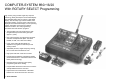
COMPUTER-SYSTEM mc-16/20 With ROTARY SELECT Programming High security using modern single chip computer technology. Newly developed LCD multi-data display with integrated static driver for precise, clear digital display. The extremely high contrast enables, even with bright sunlight, a precise check of the functions displayed in the transmitter display such as operating voltage, input data, mixer functions, settings, direction of rotation, trim and programming information with multi-function programs.
• Sub Trim system for the neutral adjustment of all Servos and adjustment of older makes of servos with inconvenient neutral. mc-16/20 • Servo Throw (adjustment of full servo travel) adjustable between 0 and 160%. Allows setting symmetrically or asymmetrically to allow the servo to move more less in one direction Sets Part No. 4838* for the 35 MHz band Part No. 4845* for the 40 MHz band * In each case the transmitter battery, 9.6v / 1.4 Âh (Part No. 3407) needs to be added separately.
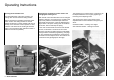
Operating Instructions Opening the Transmitter case The removable back of the case is held by one locking catch and two interlock sliding catches. Before opening the Transmitter ensure the power switch is OFF. The sliding catches are moved against the direction of arrow (inward) until they hit the stop, then case back can be opened. To close, insert the case back into the housing at the lower edge. Push it closed and then slide both caches in direction of the arrow (outward).
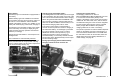
Power Supply The battery tray in the transmitter is equipped with a 9.6v battery. Different battery types are available to be selected. Into the battery mounting for the receiver, insert four AA cells of 1.2v and between 500 and 600mAh. Instead of the battery mounting, or in addition, a 4.8v battery with miniature plug can be used, see page 5. Pay attention to the full battery voltage. If the rudder moves noticeably more slowly or display the goes under 9.
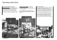
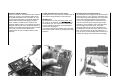
Operating Instructions Frequency band and Channel change Change frequency band: The Transmitter can be operated on different frequency bands by changing the High Frequency module. The removable HF module is held by four sprung pin fittings in the centre of the Transmitter. Two cables must be attached. Link 1 connects to the Transmitter circuit board. Link 2 connects the HF module to the aerial. Changes of the HF channels: The channel is determined by the crystal.
Fasten the NAUTIC modules Insert the module into the intended location and that check it fits correctly. The protective plastic film on the printed fascia plate can be now taken off. Then remove the backing paper of the double sided tape and the attach the fascia plate lightly pressing it down. Insert the module from the inside into the prepared module location. The module is secured by fitting the washers and nuts to the potentiometers or switches and carefully tightening them with a suitable tool.
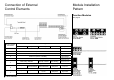
Connection of External Control Elements Module Installation Pattern Function Modules See page 91 External Switch Connection Model Type Standard “FL” Unifly “UN” F3B/Butterfly “Fb” Aerobatic “AC” Helicopter “HE” 0 Dual-Rate and Exponential for: Aileron Roll 1 Dual-Rate and Exponential for: Elevator Pitch 2 Dual-Rate and Exponential for: Rudder Tail Rotor 3 Combi-mix (Aileron Ö Rudder) Autorotation Mixer Elevator Ö Flap Throttle Pre-set (Idle Up) Collective Pitch Curve Throttle Pre-set (Id
Switches, Controls Transmitter Modules See page 91 General Section 11
Compatibility of Computer Systems mc-16/20 The mc-16/20 transmitter can be operated with all currently available Graupner FM PPM receivers, as well as other receivers with negative going pulses, from the 35 and 40 MHz frequency band. Slight reduction of servo travel can become countered by the transmitter up to a maximum of ±160%. Also the neutral position of servos attached receiver channels 1 to 8 can be adapted in ±125 steps, which is approximately ±70% of normal travel, for all 8 Servos.
Multi Data Terminal Multi Data Information Display The clear LCD MULTIDATA display with a static driver, was developed for the mc-16/20 Computer System. It offers a improved safety during operation, since all important functions are displayed. Even in bright sunlight, all the parameters on the display are represented in high contrast.
System Menu Using the system for the first time and programming the basic transmitter data Software Structure The software is divided into two menus, which are activated in different ways. 1. System Menu Adjusting the basic transmitter functions. 2. Set-Up Menu Selecting, activating and programming the model specific data. Entering the System Menu Simultaneously press the ROLL UP and ROLL DN buttons (= ENTER ) whilst turning the transmitter on. An acoustic signal sounds.
MODULATION MODE MODEL TYPE CONTROL MODE Selecting the Modulation Mode (access via System Menu) Establishing the Model Type (access via System Menu) Transmitter Stick Functions for Channels 1…4 (access via System Menu) The first option in the System Menu is to set the type of modulation. This varies depending on the type of receiver you will be using. The mc-12, mc-18, mc-20 and DS 20 mc are PCM types (Pulse Code Modulation) and are used with the transmitter set to PCM modulation.
THROTTLE DIRECTION MODEL NAME NAUTIC PROGRAM Reversing the Direction of Throttle Control (access via System Menu) Entering the Model Name (access via System Menu) Connecting Nautic Modules (only in PPM Mode) (access via System Menu) This reverse function is effective for all model types. This code provides a means to alter the direction of operation of the throttle stick (transmitter function 1) to suit your preference. You can toggle between “NORM” and “REV” by pressing the INC or DEC buttons.
DATA INITIALISATION MODEL SELECT Reset, erase data & reprogram the basic values (access via System Menu) Switching Model Memory 1 – 20 (access via System Menu) Before you re-program a model memory, you should reset all data using this code in order to ensure that all parameters and functions are reset to the default settings. When you select the “RST” function, the number of the model memory in the bottom line of the display flashes. This is the memory whose settings are to be erased.
Set-Up Menu General notes You have concluded the basic programming of the transmitter. If no special functions, like servo travel adjustment, servo reversal, mixer and coupling function etc., are necessary, you can now already put your model into operation. Look up the basic outline of the multi-function finished programs on page 26 and 27, or test them using the detailed descriptions for the model type used.
Set-Up Menu Selecting and Adjusting the Program Settings Flow Diagram of Set-Up Menu (Partial View) (includes only those functions which are common to all model types) Switch on the transmitter and press ENTER to switch to the Set-Up Menu program. (If the System Menu is active, press ENTER twice). The Multi-Data Information Display now switches from the basic information (normal operation or stopwatch) to the Set-Up Menu, and you will see the last selected function from this menu on the screen.
DUAL-RATE Switchable Servo Travel (access via Set-Up Menu) The Dual-Rate function lets you switch to a different amount of travel while the model is in flight, using an external switch. The travel for each of the two switch positions can be set to any value within the range 0 to 125% of normal servo travel. The “D/R” switches must first be connected to main circuit board in the transmitter (see page 10).
SERVO REVERSE SERVO NEUTRAL POSITION SERVO TRAVEL Reversing the Rotation of the Servos (access via Set-Up Menu) Servo Neutral Position (access via Set-Up Menu) Servo Travel Adjustment (access via Set-Up Menu) Using this option, you can reverse the direction of servo rotation. The set servo rotation is shown in the display for all servo functions 1…8; you will see the cursor line under either “REV” or “NORM”.
MIXER FUNCTIONS Freely Programmable Mixer (access via Set-Up Menu) The Multi-function menus "FL", "UN”, "Fb", "AC" and "HE" contain numerous mixing functions, with which two (or more) control functions are mixed together. For example "Combi Mix ", here the rudder can be moved at the same time, without operating the rudder stick, on operating the ailerons. Nevertheless the rudder remains separately controllable.
Programming Example Aileron as landing aid with the type of model “UN” STOPWATCH and ALARM TIMER Stopwatch and Countdown Clock (access via Set-Up Menu) In normal operating mode the display can be set to timer display with the CH SEL button. The default, without having called code “TMR”, is a stopwatch (0...999s). The Start/Stop is using either INC or DEC and reset to “000” is by using CLEAR . If the transmitter is switched off & back on, the display last selected appears, i.e. either model name or "000".
Example 2: To link the stopwatch with the throttle, CH SEL is pressed when the display shows “OF” (timer OFF). The display changes to "+-" indicating the switching direction needs to be selected using the INC / DEC buttons. This controls whether the stopwatch runs with the throttle above the neutral position, display "1H" (ch 1 = High), or below the neutral point with display “1L” (ch 1 = Low). If CH SEL is pressed again, the direction is retained and will be used later.
FAIL SAFE MEMORY and Receiver Battery FAIL SAFE Storage of Fail Safe data; only in PCM mode (access via Set-Up Menu) This function is only possible when in PCM mode and with receiver models mc-12, mc-18, mc-20 and DS 20 mc! FAIL SAFE MEMORY The higher working reliability of Pulse Code Modulation (PCM) in relation to the simple Pulse Position Modulation (PPM) results from the fact that the microprocessor built in the receiver recognizes, whether a received control signal was falsified or damaged by extern
Summary of Ready-Made Multi-Function Programs Standard (Fly) Described on page 28. Unifly Described on page 34. F3B / Butterfly Described on page 42. FL = STANDARD UN = UNIFLY Described on page 28. Described on page 34.
Fb = F3B, Butterfly AC = ACROBATIC HE = HELICOPTER Described on page 42. Described on page 52. Described on page 60.
STANDARD Block Diagram STANDARD (Fly) “FL” Model Type Described Included under the STANDARD type are all motor and sailplane models, with which control over elevator, rudder, ailerons, engine throttle or rpm (and/or airbrakes for sailplane models) is possible. In this programme it is also possible, via additional control paths for auxiliary functions, to control features like retractable landing gear, cable release, mixture adjustment or also landing flaps (and/or variable flaps for sailplane models).
Fixed Wing Models 29
Set-up Diagram Model Type “FL” = STANDARD All the mixers and adjustment values are set to 0 (= mixer off). To adjust the mixer and adjustment values, while flying, we recommend fitting the 2-way momentary switch, Part No. 4160.44 (see page 10) All mixer data can be reset to 0 by pressing the CLEAR button, i.e. turned off. When the display shows “OF” the external switch controlling the mixer is switched off.
For your Notes Fixed Wing Models 31
COMBI-MIX FLAP ELEVATOR MIXER ELEVATOR MIXER FLAP Aileron Rudder Mixer (access via Set-Up Menu) Flap Elevator Mixer (access via Set-Up Menu) Elevator Flap Mixer (access via Set-Up Menu) When an aileron command is given, the rudder also moves to a pre-programmed extent. The rudder can be separately steered at any time with priority over the mixer. After calling the code, the INC and DEC buttons are used to adjust the ratio up to the maximum of ±125%.
WING TYPE PROGRAMS For your Notes Wing Mixer for V-Tail, Delta and Tailless models (access via Set-Up Menu) 1. For models with a V-tail, "VTL", must be used to mix the functions of elevator and rudder. Elevator function: Both surfaces of the V-tail move in the same direction. The mix relationship is adjustable by the dual-rate function for channel 3, see page 20. Rudder function: The surfaces of the V-tail move in opposite directions.
UNIFLY Model Type Described In contrast to the Standard model type, the "UNIFLY" type is used where separate aileron servos are used, in place of a single common servo, which are by already software coupled. This permits independent adjustment of the aileron deflections upward and downward, which allows a differential mixer to be used. In addition, the separate controlling of the aileron surfaces makes it possible to operate the both surfaces in the same direction giving a flap function, or Flaperons, e.g.
Fixed Wing Models 35
Set-up Diagram Model Type “UN” = UNIFLY All the mixers and adjustment values are set to 0 (= mixer off). To adjust the mixer and adjustment values, while flying, we recommend fitting the 2-way momentary switch, Part No. 4160.44 (see page 10) All mixer data can be reset to 0 by pressing the CLEAR button, i.e. turned off. When the display shows “OF” the external switch controlling the mixer is switched off.
Fixed Wing Models 37
FLAP FLAPERON MIXER COMBI-MIX DIFFERENTIAL MIXER Flap Flaperon Mixer (access via Set-Up Menu) Aileron Rudder Mixer (access via Set-Up Menu) Aileron Differential Mixer (access via Set-Up Menu) The mixer "F-A" allows an adjustable portion of the flap control system to be fed to the aileron channels (2 and 5) so that the ailerons move with flap deflection in a manner like the flaps, but normally with smaller movement. The advantage is that a more even lift distribution over the span can be achieved.
FLAP ELEVATOR MIXER ELEVATOR MIXER FLAP Flap Elevator Mixer (access via Set-Up Menu) Elevator Flap Mixer (access via Set-Up Menu) During slow flight when extending flaps, automatic proportionally correction of elevator is made, thus the pitch attitude of the model becomes independent of the position of the flaps. The mix portion is entered in the code "F-E", the INC and DEC buttons, between 0 and ±125%. Next the mixer neutral point must be specified.
V-TAIL MIXER SPOILER ELEVATOR MIXER Mixer for Models with V-Tails (access via Set-Up Menu) Spoiler Elevator Mixer (access via Set-Up Menu) For models with a V-tail the functions of elevator and rudder must be mixed so with one another so that during elevator movement both surfaces are moved up or down in the same direction, and during rudder control the surfaces move in opposite directions , i.e. one surface upward and the other downward.
For your Notes Fixed Wing Models 41
F3B/BUTTERFLY Model Type Described The F3B/BUTTERFLY type is intended for F3B competition models. It can be used, however, for other similar models. Depending on the external switches connected, functions can be switched on and off. Beside two aileron servos, it is intended that two separate flap servos are used. This allows mixing flap elevator and/or elevator flap. Also the combi and differential functions plus flap flaperon and V-tail mixers with three further finished coupling functions.
Fixed Wing Models 43
Set-up Diagram Model Type “Fb” = F3B/BUTTERFLY 44 Fixed Wing Models All the mixers and adjustment values are set to 0 (= mixer off). To adjust the mixer and adjustment values, while flying, we recommend fitting the 2-way momentary switch, Part No. 4160.
Fixed Wing Models 45
FLAP FLAPERON MIXER COMBI-MIX DIFFERENTIAL MIXER Flap Flaperon Mixer (access via Set-Up Menu) Aileron Rudder Mixer (access via Set-Up Menu) Aileron Differential Mixer (access via Set-Up Menu) The mixer "F-A" allows an adjustable portion of the flap control system to be fed to the aileron channels (2 and 5) so that the ailerons move with flap deflection in a manner like the flaps, but normally with smaller movement. The advantage is that a more even lift distribution over the span can be achieved.
FLAP ELEVATOR MIXER ELEVATOR MIXER FLAP Flap Elevator Mixer (access via Set-Up Menu) Elevator Flap Mixer (access via Set-Up Menu) During slow flight when extending flaps, automatic proportionally correction of elevator is made, thus the pitch attitude of the model becomes independent of the position of the flaps. The mix portion is entered in the code "F-E", the INC and DEC buttons, between 0 and ±125%. Next the mixer neutral point must be specified.
FLAP FLAPERON MIXER Flap Flaperon Mixer (access via Set-Up Menu) For models with a V-tail the functions of elevator and rudder must be mixed so with one another so that during elevator movement both surfaces are moved up or down in the same direction, and during rudder control the surfaces move in opposite directions , i.e. one surface upward and the other downward. The "VTL" Program contains the appropriate mixer, to control surfaces connected to separate servos.
SPOILER ELEVATOR MIXER Spoiler Elevator Mixer (access via Set-Up Menu) Due to the changing lift when extending the spoilers, the elevator must be adjusted by an appropriate amount to compensate. The elevator compensation can be adjusted between 0 and ±125% of the spoiler stick travel for use during the landing approach (0% = mixers inactively). A switch connected to socket 7 of the transmitter board, allows this function to be changed between two options "SE0" and "SE1" (spoiler elevator).
SPOILER MIXER FLAP Spoiler Flap Mixer (access via Set-Up Menu) With movement of the throttle/spoiler control stick (control function 1) both aileron servos can be adjusted for landing using the INC / DEC buttons from 0 to ±125% (0% = mixer inactive). A switch connected to socket 7 of the transmitter board, allows this function to be changed between two options "SF0" and "SF1" (spoiler flaps). The mixer must have the position, of control function 1, set that corresponds to normal flight, i.e.
For your Notes Fixed Wing Models 51
ACROBATIC Model Type Described The basic version of this program allows Motor (or airbrake), Aileron, Elevator, Rudder, Flap and Spoiler. Receiver outputs 5 and 8 are available for auxiliary functions, e.g. retractable undercarriage, mixture control for the motor, etc. Also included is a ready made mixer for Elevator Flap mixing. Other mixing functions can be achieved using the 3 freely programmable mixers available. The Combi-mixer for aileron rudder mixing is available.
Fixed Wing Models 53
Set-up Diagram Model Type “AC” = ACROBATIC 54 Fixed Wing Models All the mixers and adjustment values are set to 0 (= mixer off). To adjust the mixer and adjustment values, while flying, we recommend fitting the 2-way momentary switch, Part No. 4160.
Fixed Wing Models 55
AUTOMATIC MANOEUVRE DUAL-RATE / EXPOAUTO-COUPLING Two Snap-Roll programs (access via Set-Up Menu) Automatic switching of control characteristics (access via Set-Up Menu) The switches to operate the Snap-Roll program must be connected to socket 6 and/or 7 of the transmitter board. This code allows the programming of aileron, elevator and rudder positions, plus the pre-setting of the throttle position. Two Snap-Roll programs are available, i.e. Snap-Roll to left and right.
AUTO-LANDING Automatic Landing Assistance (access via Set-Up Menu) Around the landing approach, in particular to reduce the speed of very fast F3A models, this code offers the possibility, when falling below a certain preselectable engine speed, of putting the elevator and flaps into a defined position. Both functions, however, remain separately controllable. Optionally an airbrake / spoiler can also be driven out.
COMBI-MIX If the "ALD" subroutine were previously switched off by pressing CLEAR , can move the elevators, flaps and airbrake to their pre-determined auto-landing positions by operating external switch 5. The settings for the control surfaces must be determined experimentally during flight and then adapted to the requirements.
WING TYPE PROGRAMS Wing Mixer for Delta and Flaperon models (access via Set-Up Menu) After calling this program "WNG OF" appears in the Info-Display . Two special mixers are available with this code, which can be selected using INC/DEC. 1. For Delta models, "DLT" combines the functions of Ailerons and Elevators, where the servos are connected to receiver outputs 2 and 3 (Throttle to 1, Rudder to 4).
HELICOPTER MODELS – General Information With these helicopter programs the mc-16/20 transmitter provides all the options for the controlling a modern model helicopter.
Programming a Helicopter, model type “HE” The initial set-up of the transmitter for helicopter models is achieved using the System Menu, see pages 14 – 17. The basic set-up depends less on the model itself than on the general control preferences of the pilot. The most important setting, above all others, is the control mode (MOD), including whether the throttle stick should pushed or pulled for maximum pitch (THR). Both settings should be reviewed in all cases before beginning with the set-up of the model.
HELICOPTER MODELS Allocation of Receiver Connections (Ch 1 – 8) The servos must be connected to the radio receiver as shown in the diagrams below: 62 Helicopter Block Diagram for the HELICOPTER “HE” Program *) Gyro Part No Mini-Gyro 3274 NEJ-120BB 3277 NEJ-120BB ECO 3278 *) Gyro NEJ-1001 Piezo 2000 Part No 3906 3285
Helicopter 63
Set-up Diagram Model Type “FL” = STANDARD 64 Helicopter All the mixers and adjustment values are set to 0 (= mixer off). To adjust the mixer and adjustment values, while flying, we recommend fitting the 2-way momentary switch, Part No. 4160.
Connections to the receiver (Ch 1 to 8) The servos must be connected to the receiver outputs as shown below: Helicopter 65
HELICOPTER Adjustment Instructions Programming System The following programming guidance orients itself around the practical programming conditions and not at the consequence of the options in the transmitter. For the initial programming of a helicopter it is advisable to observe this order since it represents a logical operational sequence.
SWASHPLATE TYPE Swashplate Mixer (access via Set-Up Menu) Four different programs exist for the control of the swashplate: “N” (Normal) The swashplate is tilted for roll by a servo; the collective pitch control is by a separate servo. Type “N” also includes those helicopters with mechanic mixers to achieve the collective and cyclic blade control.
SERVO REVERSE SERVO NEUTRAL POSITION SERVO TRAVEL Reversing the Rotation of the Servos (access via Set-Up Menu) Servo Neutral Position (access via Set-Up Menu) Servo Travel Adjustment (access via Set-Up Menu) Reversing the direction of servo rotation. The set servo rotation is shown in the display for all servo functions 1…8; you will see the cursor line under either “REV” or “NORM”. This eliminates the need to reconnect plugs in the transmitter or reverse the servos themselves.
Setting the Throttle and Collective Pitch curves: Fundamental Explanations Setting the Throttle and Collective Pitch The tuning of throttle and collective pitch, and thus the performance curve of the engine and collective pitch control, is the most important adjustment procedure with a helicopter model.
Throttle and Collective Pitch curves: Practical Procedure Basic Adjustment Although the pitch and throttle curves can be set electronically over a wide range in the mc-1620 transmitter, the hovering point of the helicopter should be at least approximately correctly preset mechanically (see introduction). If you pay attention to the instructions of the respective helicopter kit for adjusting the controls this is usually the case.
Descending Flight Setting During the previous setting it was assumed that any external switches possibly attached for throttle and pitch curve change-over were in the basic position, i.e. that for the hovering flight throttle setting "TM0" (or without an external switch the only option available is "TM1" which was used instead of "TM0"). This switching position is always selected when starting the engine and the rotor.
Throttle Curve Throttle Curve (Low, Middle, High) (access via Set-Up Menu) Three different profiles for the carburettor response can be adjusted and called up in flight by external switches; the function of the throttle pre-select is included in this changeover. The curves are determined in each case by three points: • The low collective pitch / throttle stick position, called "TL..." (Throttle Low), • The middle collective pitch / throttle stick position, called "TM...
Examples of setting the Throttle pre-select Throttle Low – "TL0", "TL1", "TL2" With this option you can programme three alternative throttle pre-selects for different flight tasks. Throttle Middle – “TM0”, “TM1”, “TM2” With “TM0” through “TM2”, three alternative hover point throttle settings can be programmed.
Pitch Curve Pitch Curve (Low, Middle, High) (access via Set-Up Menu) Four different profiles for the collective pitch response can be adjusted and called up in flight by external switches. Three curves are available for normal flight (under motor power), and a separate curve is available for autorotation. The curves are determined in each case by three points: • The low collective pitch / throttle stick position, called "PL...
Examples of setting the Throttle pre-select Pitch Low – "PL0", "PL1", "PL2" For the three throttle pre-select settings "TL0", "TL1" and / or. "TL2" different low collective pitch values are programmable. Operation of the autorotation switch in socket 3 allows a fourth low collective pitch value "PLA" to be programmed. Pitch Middle – “PLM” With this option the pitch value for the hovering flight is set.
AUTOROTATION Switching to Autorotation (access via Set-Up Menu) Autorotation is a helicopter flight condition, in which the main rotor is no longer powered by the engine but by the air flow trough the rotor in descending flight. So that sufficient main rotor RPM remains, the rotor blades must be brought, with the collective pitch control stick, to a suitably small angle of incidence. The ground approach angle lies depends on the wind strength and is between 45° (zero wind) and 80° (strong wind).
STATIC TORQUE COMPENSATION DYNAMIC TORQUE COMPENSATION Static Mixer (access via Set-Up Menu) Dynamic Mixer (access via Set-Up Menu) Using this option the static torque compensation (Pitch Î Tail) can be adjusted, separately for the climbing, indicated "STH", and descending flight, indicated "STL" representing above and below the collective pitch control stick central position.
Gyro Control Automatic Gyro Gain Control (access via Set-Up Menu) With this option you can reduce the effect of the Gyro sensor with increasing tail rotor stick excursion. This will only work with a gyro system which allows the gain to be control from an auxiliary channel of the transmitter. In central position of the tail rotor control stick and a proportional module attached at socket CH 7 of the transmitter plate the set gyro effect results.
Example: 1. Adjuster 1: Left stop, Adjuster 2: Maximum, Gyro Mix at 100% 3. Adjuster 1: Left stop, Adjuster 2: Maximum, Gyro Mix at 60% With the slider control 7 the gyro effect can be set anywhere from "0" up to the maximum. During operation of the tail rotor control the gyros effect has a linear reduction, where the "0" value is reached at stick full travel position. In contrast to example 1 the gain reduction is when the tail rotor control stick has moved 60% of its travel. 2.
Freely Programmable Mixer Free Programmable Mixer (access via Set-Up Menu) Additional to the pre-programmed mixer functions contained in the helicopter program are two freely selectable mixers, which are characterized by the letters A and B and the number of the input function and the output channel. The lower display line will show either the mix portion and direction, or "OF" if the mixer is switched off using the associated external switch. Setting example for mixer "A" 1. Channel Selection.
DUAL-RATE Switchable Servo Travel (access via Set-Up Menu) The Dual-Rate function lets you switch to a different amount of travel while the model is in flight, using an external switch. The travel for each of the two switch positions can be set to any value within the range 0 to 125% of normal servo travel. The “D/R” switches must first be connected to main circuit board in the transmitter (see page 10).
STOPWATCH and ALARM TIMER Stopwatch and Countdown Clock (access via Set-Up Menu) In normal operating mode the display can be set to timer display with the CH SEL button. The default, without having called code “TMR”, is a stopwatch (0...999s). The Start/Stop is using either INC or DEC and reset to “000” is by using CLEAR . If the transmitter is switched off & back on, the display last selected appears, i.e. either model name or "000". The code “TMR” allows the application possibilities to be extended: 1.
FAIL SAFE MEMORY and Receiver Battery FAIL SAFE Storage of Fail Safe data; only in PCM mode (access via Set-Up Menu) This function is only possible when in PCM mode and with receiver models mc-12, mc-18, mc-20 and DS 20 mc! FAIL SAFE MEMORY The higher working reliability of Pulse Code Modulation (PCM) in relation to the simple Pulse Position Modulation (PPM) results from the fact that the microprocessor built in the receiver recognizes, whether a received control signal was falsified or damaged by extern
NAUTIC Multi-Prop Modules Only available in PPM Mode Optional Transmitter Module NAUTIC Multi-Proportional Module Part No. 4141 Up to two modules are connectable, (Described on page 92) Function Notes The NAUTIC Multi-Prop module allows two proportional function channels be split into eight proportional channels, i.e. at the receiver connections three additional servo connections are available per module. Two prop.
Receiver Requirements NAUTIC Multi-Prop Decoder Part No. 4142 (Described on page 92) Remark For each NAUTIC Multi-Prop module a NAUTIC Multi-Prop decoder is necessary. Note: The NAUTIC Multi-Prop decoder extends two proportional channels (1 servo each), for a transmitter fitted with the NAUTIC Multi-Prop module, to eight proportional channels (4 servos each). For a trouble free function at least three of the four possible servos should be attached to the NAUTIC Multi-Prop decoder.
NAUTIC Expert Switch Function Modules Only available in PPM Mode Optional Transmitter Module 16 Channel NAUTIC Expert Module Part No. 4108 Up to two modules are connectable, (Described on page 92) Function Notes The NAUTIC Expert module extends two proportional channels to 16 signal paths. All eight switches have a central position, providing a genuine forwards– stop–backwards function, if at the receiver a switch module, Part No. 3754.1 or a Dual-Switch module Part No. 3754.2 is used.
Receiver Requirements Part No. Module 4159 2 / 16 channel NAUTIC Expert switch element (see page 92) 3941.6 Socket with 3core lead 3936 or 3936.1 Y-lead 320 with 100mm cable length 3754.1 NAUTIC Switch Module 3754.2 NAUTIC Dual-Switch Module Comments This module is required for the transmitter switch module to work For connecting devices, max. 0.
NAUTIC Multi-Prop and Expert Switch Modules Only available in PPM Mode Receiver Requirements Part No. Module Optional Transmitter Module Comments 4142 NAUTIC Multi-Prop Decoder 4 servos connected 4159 2-16 channel NAUTIC Expert Switch Module For 16 switch functions 3941.6 Socket with 3-core lead For connection of devices max. 0.7 A per signal path 3939 or Y-Lead 320 with 100 mm For connection of NAUTIC 3936.1 cable length Switch or Dual-Switch modules 3754.
Connection example for submarine SEABEX ONE Proportional Functions Tail propeller direction drive servo right/left Tail propeller motor drive forward–stop– backward Tail propeller direction drive servo right/left Tail propeller motor drive forward–stop– backward Dual-Switch Functions (Connected via a Y-Lead, Part No.
ERROR MESSAGE Storage Error This message appears in the case of an error of the internal memory, i.e. all the entered data has been deleted and the memory contents reverted to the standard values! The error can be caused by the complete discharge of the lithium battery on the transmitter plate. It has a duration of up to approx.
Switches & Modules Momentary Switch Part No. 4160.11 Sprung-off for momentary switching functions. 2 channel Switch Module Part No. 4151 with long arm Part No. 4151.1 with short arm 2-way Momentary Switch Part No. 4160.44 Used in place of INC/DEC for and required as a start/stop key for stopwatch The switch has 3 positions, so that for example electric motors can be switched forward-stop-backwards. Also for suitable on/off functions, like switching loads, lamps, etc.
NAUTIC Modules 16 Ch NAUTIC Expert Switch Module Part No. 4108 This module extends 2 channels to 16 switch outlets. All 8 switches have a central position, which makes it possible to switch a function forwardstop-backwards where required. 3 switches are sprung-off and 2 are sprung-off in one direction. 2 models can be mounted in the transmitter, and together providing 32 switch functions. For each module, the receiver requires a 2-16K NAUTIC Expert Switch module (part No. 4159).
Receivers Miniature SUPERHET C 12 12 Channel Narrow Band Receiver Part No. 3175 for the 35MHz band Part No. 4075 for the 40MHz band Mini SUPERHET mc-18 18 Ch FM/PCM Narrow Band Receiver Part No. 3171 for the 35MHz band Part No. 4071 for the 40MHz band Miniature SUPERHET C 16 16 Channel Narrow Band Receiver Part No. 3867 for the 35MHz band Part No. 4067 for the 40MHz band Mini SUPERHET mc-20 20 Ch FM/PCM Narrow Band Receiver Part No. 3176 for the 35MHz band Part No.
Accessories for Transmitters Push Button Part No. 4144* With pressure on the button the switch is operated and it releases to the "off" only when pressing the button again position. The Push Button can be changed, by removing a locking link, to a momentary button, where the function remains "on" only whilst the button is pressed. Flexible Antenna Flexible short antenna for optimal freedom of movement and unrestricted use of the transmitter.
Transmitter Suspension System Part No. 1127 Neck Strap Part No. 1125 The retaining arms can be locked in the stowed and working positions. The entire transmitter upper surfaces is accessible and unhindered. It features holes for the attachment of a neck strap. Adjustable length, 30mm wide and fitted with attachment clips. PROFI Transmitter Tray Part No. 3082 Wide hand rest surfaces make possible sensitive, precise steering even over extended periods. The outer is shaped with a double bowl technology.
Teach – Pupil System with Fibre-Optic Cable Opto-electrical Teach-Pupil System with Fibre-optic cable Part No. 3290 The teacher and pupil transmitters may be operated only in the PPM mode. Function Notes Switch the transmitters into PPM mode. For connection between transmitter types D 14, FM 414, FM 4014, FM 6014, FM 6014 / PCM 18, mc-14, mc-15, mc-16, mc-16/20, mc-17, mc-18 and mc-20. Plug M of the teacher-pupil cable into teacher’s transmitter, and insert plug S into the pupil’s transmitter.
Supplementary Information Use of the Remote Control System Treat your remote control equipment carefully to ensure that it is always reliable and ready for use. Switch on the transmitter first, only then switch on the receiver. Switch off the receiver first and only then switch off the transmitter. If this sequence is not observed, i.e. the receiver is switched on first with transmitter switched off, the receiver can affected by other signals and unpredictable results can occur.
Quartz Crystals, Frequency Pennants 98 Supplement
Technical Data Technical Data – Computer Transmitter mc-16/20 FM/FMsss switchable to PCM with single chip Transmission System micro computer system Technical Data – HF Transmitter Module 4824.35 for 35 MHz band Part No. – HF Module 4824.
General Permissions Transmitter and Receiver for the 27 and 40 MHz bands are registered and can be used without charge. General permission for a Radio concerning the remote control of models Auxiliary information for manufacturers, trading companies, salesmen and purchasers (Version dated 15.4.1987) 1.
Customer Approvals for Transmitter mc-16/20 35 MHz GRAUPNER / JR mc-16 Approval Number A 400272 V FE for FM and PCM Receivers 35 MHz C 16 FMsss 35 S C 18 FMsss 35 S mc-18 35 S mc-20 35 S Approval Number FE-61/81 40 MHz 40 MHz GRAUPNER / JR Approval Number G 400273 V MF mc-16 C 16 FMsss 40 S C 18 FMsss 40 S mc-18 40 S mc-20 40 S Approval Number MF-110/81 Supplement 101
Customer Approvals for FM Receivers 35 MHz C 12 FM 35 S Approval Number A 012804 B FE 40 MHz C 12 FM 35 S Approval Number G 012803 B MF 102 Supplement 35 MHz C 19 FM 35 S Approval Number A 106898 D FE 40 MHz C 19 FM 40 S Approval Number G 106897 D MF
Customer Approvals for PCM Receivers and Dual-Conversion Superhet 35 MHz 35 MHz mc-12 PCM 35 S DS 18 FM 35 DS 20 mc-35 Approval Number A 103692 C FE Approval Number A 400090 A FE 40 MHz 40 MHz mc-12 PCM 40 S DS 18 FM 40 DS 20 mc-40 Approval Number G 103691 C MF Approval Number G 400091 A MF Supplement 103
JOHNANNES GRAUPNER POSTFACH 1242 D-73220 KIRCHHEIM-TECK GERMANY Printed in Germany – 7/93 The right to make changes is reserved. Supply only to the specialist trade. Sources of supply can be proven.