
Operation Manual


General Section 9
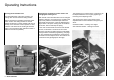
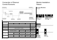
Fasten the NAUTIC modules
Insert the module into the intended location and that
check it fits correctly. The protective plastic film on
the printed fascia plate can be now taken off. Then
remove the backing paper of the double sided tape
and the attach the fascia plate lightly pressing it
down. Insert the module from the inside into the
prepared module location. The module is secured by
fitting the washers and nuts to the potentiometers or
switches and carefully tightening them with a suitable
tool. Finally, mount the control knobs to the
potentiometers so they correspond with the scale
markings.
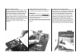
Length adjustment of the control sticks
The length of the control sticks can be adjusted up to
the maximum length marking on the stick shaft.
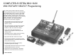
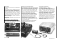
INC/DEC Keys
By installation of a 2 way momentary switch, Part.
No. 4160.44, the functions of the INC / DEC keys
can be taken over. The connection is made to the
sockets marked INC and DEC on the transmitter
circuit board, see page 10.
The switch increases the operating ease, especially
when model-specific values are programmed during
operation.
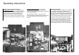
Assembly of the Transmitter Carriers
The transmitter can be equipped with the transmitter
mounting Part. No. 1127. Open the transmitter case
and in remove the bottom blanking caps. The bottom
of the case is already prepared for the assembly.
The four mounting plate holes in the bottom of the
case can be opened up by boring through using a
screwdriver. From inside the case, insert the metal
arms through the mounting holes. The plastic
mounting plates are fed over the metal arms and
screwed to the outside of the case, with two screws
each. The carrier arms are strongly retained up a
long coil spring. If softer folding of the carrier arms is
required, the spring must be shortened accordingly.