
User's Manual

101
Program description: helicopter mixers – model helicopter
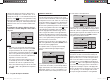
already fully open and no further power increase is pos-
sib
le (this assumes that the motor is correctly adjusted),
then you should reduce the maximum blade pitch angle
at full defl ection of the collective pitch stick, i. e. the value
at Point 5. Conversely, if motor speed rises during the
vertical climb, you should increase the pitch angle. This
is done on the “Collective pitch” graphic page by moving
the vertical line to Point 5 using the collective pitch stick,
and changing its value accordingly using the arrow but-
tons cd of the right-hand four-way button.
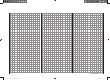
This diagram shows the changes
to the collective pitch maximum
value only.
+100%
-100%
OUTPUT
234 51
Control travel
Hover
point
Now bring the model back to the hover, which again
should coincide with the mid-point of the Ch 1 stick.
If you fi nd that the collective pitch stick now has to be
moved from the mid-point in the direction of “higher”,
then you should correct this deviation by slightly increas-
ing the collective pitch angle at the hover - i. e. Point
3 - until the model again hovers at the stick centre point.
Conversely, if the model hovers below the mid-point, cor-
rect this by reducing the pitch angle once more.
You may fi nd that it is also necessary to correct the
throttle opening at the hover point (Point 3) in the “Ch 1
¼ throttle” menu.
of this manual for a full explanation of the digital trims.
Around the mid-point of the collective pitch stick the
model should lift off the ground and hover at approxi-
mately the rotational speed you wish to use. If this is not
the case, correct the settings as follows:
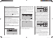
1. The model does not lift off until the collective
pitch stick is above the centre point.
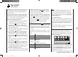
a) Rotational speed too low
Remedy: on the “Ch 1
¼ throttle” graphic page,
increase the value at Point
3.
+100%
-100%
OUTPUT
234 51
Control travel
Hover
point
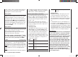
b) Rotational speed too high
Remedy: on the “Collec-
tive pitch” graphic page,
increase the blade pitch
angle for collective pitch
by increasing the value at
Point 3.
+100%
-100%
OUTPUT
234 51
Control travel
Hover
point
2. The model lifts off below the centre point.
a) Rotational speed too high
Remedy: on the “Ch 1
¼ throttle” graphic page,
reduce the throttle opening
by reducing the value at
Point 3.
+100%
-100%
OUTPUT
234 51
Control travel
Hover
point
b) Rotational speed too low
Remedy: on the “Collective
pitch” graphic page, re-
duce the blade pitch angle
by reducing the value at
Point 3.
+100%
-100%
OUTPUT
234 51
Control travel
Hover
point
Important:
It is important to persevere with this adjustment pro-
cedure until the model hovers at the correct rotational
speed at the centre point of the throttle / collective pitch
stick. All the other model settings depend upon the cor-
rect setting of these parameters!
The standard set-up
The remainder of the standard adjustment procedure
is completed on the basis of the fundamental set-up
which you have just carried out, i. e. we now assume that
the model hovers in normal fl ight at the centre point of
the throttle / collective pitch stick, with the correct rotor
speed. This means that your model helicopter is capable
of hovering and also fl ying circuits in all phases whilst
maintaining a constant system rotational speed.
The climb setting
The combination of throttle hover setting, collective pitch
setting for the hover and the maximum collective pitch
setting (Point 5) now provides you with a simple method
of achieving constant system rotational speed from the
hover right to maximum climb.
Start by placing the model in an extended vertical climb,
holding the collective pitch stick at its end-point: motor
speed should not alter compared with the hover setting.
If motor speed falls off in the climb, when the throttle is
33112_mx12_HoTT_2_GB.indd Abs33:10133112_mx12_HoTT_2_GB.indd Abs33:101 06.06.2011 19:39:4106.06.2011 19:39:41