
User's Manual


102
Program description: helicopter mixers – model helicopter
in premature wear of the clutch and gear train. The main
rotor b
lades are generally free to swivel, and they may
be unable to keep pace with such swift acceleration, in
which case they might respond by swinging far out of
their normal position, perhaps resulting in a boom strike.
Once the motor is running, you should slowly in-
crease system rotational speed using the throttle limiter.
Important fi nal notes
Before you start the motor, check carefully that the throt-
tle limiter is completely closed, so that the throttle can
be controlled by the Ch 1 trim lever alone. If the throttle
is too far open when you switch the transmitter on, you
will see and hear a warning. If you ignore this and start
the motor with the throttle too far advanced, there is a
danger that the motor will immediately run up to speed
after starting, and the centrifugal clutch will at once
engage.
For this reason you should:
always grasp the rotor head fi rmly
when starting the motor.
However, if you accidentally start the motor with the
throttle open, the rule is this:
Don’t panic!
Hang on to the rotor head regardless!
Don’t let go!
Immediately reduce the throttle limiter, even though
there may be a risk of damaging the helicopter’s drive
train, because:
it is vital that YOU ensure
that the helicopter cannot possibly
move off by itself in an uncontrolled manner.
The cost of repairing a clutch, a gearbox or even the
motor itself is negligible compared with the damage
which a model helicopter can cause if its spinning rotor
blades are allowed to wreak havoc.
Make sure that nobody else is standing
in the primary hazard zone around the helicopter.
You must never switch abruptly from idle to the fl ight set-
ting by suddenly increasing system rotational speed, as
this would cause the rotor to accelerate quickly, resulting
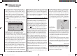
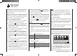
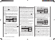
This diagram only shows the
change in the hover point, i. e. col-
lective pitch minimum and maxi-
mum have been left at -100% and
+100% respectively.
+100%
-100%
OUTPUT
234 51
Control travel
Continue adjusting these settings until you really do
achieve constant main rotor speed over the full control
range between hover and climb.
The descent adjustment should now be carried out from
a safe height by fully reducing collective pitch to place
the model in a descent from forward fl ight; adjust the col-
lective pitch minimum value (Point 1) so that the model
descends at an angle of 60 … 80°. This is done on the
“Collective pitch” graphic page by moving the vertical
line to Point 1 using the collective pitch stick, and adjust-
ing the value accordingly using the arrow buttons of the
right-hand four-way button.
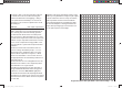
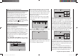
As an example, this diagram
shows the changes in the collec-
tive pitch minimum value only.
+100%
-100%
OUTPUT
234 51
Control travel
Hover
point
Once the model descends reliably as described, adjust
the value for “Throttle minimum” - the value of Point 1 on
the graph of the “Ch 1 ¼ throttle” mixer - so that system
rotational speed neither increases nor declines. This
completes the set-up procedure for throttle and collec-
tive pitch.
33112_mx12_HoTT_2_GB.indd Abs33:10233112_mx12_HoTT_2_GB.indd Abs33:102 06.06.2011 19:39:4106.06.2011 19:39:41