
User's Manual

104
Program description: helicopter mixers / auto-rotation settings
Helicopter mixers
Auto-rotation settings
Auto-rotation allows full-size and model helicopters to
land safely in a crisis, i. e. if the power plant should fail.
It can also be used if the tail rotor should fail, in which
case cutting the motor and carrying out an auto-rotation
landing is the only possible way of avoiding a high-
speed uncontrollable rotation around the vertical axis,
invariably terminating in a catastrophic crash. And that is
the reason why switching INTO auto-rotation occurs with
zero delay.
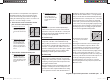
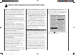
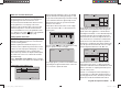
When you switch to the auto-rotation phase the helicop-
ter mixers change as shown in this screen shot:
tail
ptch
thro
Autorot
gyro
0%
SEL
0%
–90%
swash lim. off
During an auto-rotation descent the main rotor is not
dr
iven by the motor; it is kept spinning only by the
airfl ow through the rotor disc caused by the speed of the
descent. The rotational energy stored in the still spinning
rotor can be consumed to allow the machine to fl are out,
but this can only be done once. For this reason “autos”
are only likely to be successful if the pilot has plenty of
experience in handling model helicopters, and has also
set up the appropriate functions with great care.
Once you have suffi cient experience you should practise
auto-rotation landings at regular intervals, not only so
that you can demonstrate your all-round fl ying skill by
fl ying the manoeuvre in competitions, but also so that
you are in a position to land the helicopter undamaged
from a great height if the motor should fail. For this
purpose the program provides a range of adjustment fa-
cilities which are designed to help you fl y your helicopter
in its unpowered state. Please note that the auto-rotation
setting takes the form of a complete fourth fl ight phase,
for which all the adjustment facilities are available which
can be varied separately for all fl ight phases, especially
trims, collective pitch curve settings etc.
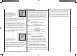
ptch (Collective pitch curve (Ch1 ¼ pitch))
In powered fl ight the maximum blade pitch angle is
limited by the motor power which is available; however,
in auto-rotation the angle is only limited by the point
at which the airfl ow over the main rotor blades breaks
away. Nevertheless, to provide suffi cient upthrust even
when rotational speed is falling off, it is necessary to
set a greater maximum collective pitch value. Press the
central SET button of the right-hand four-way button
to select the g
raph page of “Collective pitch”, and then
move the vertical line to Point 5 using the transmitter
stick. Start by setting a value which is about 10 to 20%
higher than your normal collective pitch maximum. Do
NOT set a much higher value compared with normal
fl ight initially, because collective pitch control will then
differ too greatly from the machine’s usual response
after you have thrown the switch. The danger is that you
will over-control the helicopter, and it may balloon up
again during the fl are following the auto-rotation de-
scent. If this happens, the rotational speed of the main
rotor will quickly decline to the point where it collapses,
and the helicopter ends up crashing to the ground from
a considerable height. Later, after a few trial autos, you
may wish to adjust the value again.
Under certain circumstances the collective pitch mini-
mum setting may also differ from the normal fl ight set-
ting; this depends on your piloting style for normal fl ying.
In any case you must set a suffi ciently generous collec-
tive pitch minimum value at Point 1 to ensure that your
model can be brought from forward fl ight at moderate
speed into a descent of around 60 ... 70° when collec-
tive pitch is reduced to minimum. Most helicopter pilots
already use such a setting for normal fl ying, and if this
applies to you, you can simply adopt the same value.
If you normally allow your model to “fall” at a shallower
angle, increase the value for “Point 1”, and vice versa.
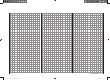
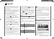
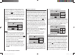
Approach angle
under varying wind
conditions.
Approach angle
in moderate
wind
no wind
45°
60°
75°
in strong
wind
For auto-rotation the collective pitch stick itself may not
be positioned right at the bottom of its travel; typically it
will be between the hover position and the bottom end-
point, giving the pilot scope for correction if necessary,
i. e. the chance to adjust the model’s pitch inclination
using the pitch-axis control.
You can shorten the approach by pulling back slightly on
the pitch-axis stick and gently reducing collective pitch,
or alternatively extend the approach by pushing forward
on the pitch-axis stick and gently increasing collective
pitch.
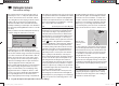
Throttle (throttle curve)
In a competition the pilot is expected to cut the motor
completely, but for practice purposes this is certainly
inconvenient, as after every practice “auto” landing you
would have to start the motor again.
33112_mx12_HoTT_2_GB.indd Abs35:10433112_mx12_HoTT_2_GB.indd Abs35:104 06.06.2011 19:39:4106.06.2011 19:39:41