
User's Manual

108
Program description: free mixers
ies according to the function which has been assigned
to it in the “Basic settings” menu (pages 56 and 64) in
the “Motor at Ch 1” column for fi xed-wing models.
Additional special features of free mixers
If you set up a mixer whose input is the same as its
output, e. g. “c1 ¼ c1”, exotic results can be obtained
in conjunction with the option of switching a free mixer
on and off. You will fi nd one typical example of this on
pages 152 … 154.
Before we come to setting mixer ratios, we have to
consider what happens if a mixer input is allowed to act
on the pre-set coupling of aileron servos, fl ap servos or
collective pitch servos:
Fixed-wing models:•
Depending on the number of wing servos set in the
“Aileron / Flap” line of the “Basic settings” menu,
receiver outputs 2 and 5 are reserved for the aileron
servos, and outputs 6 and 1 for the two fl ap servos,
as special mixers are assigned to these functions.
If mixer outputs are programmed to this type of cou-
pled function, you have to consider their effect on the
associated pair of wing fl aps, according to the “re-
ceiving” control channel:
Mixer Wirkung
NN * ¼ 2 Servo pair 2 + 5 responds with aileron
function
NN * ¼ 5 Servo pair 2 + 5 responds with fl ap
function
NN * ¼ 6 Servo pair 6 + 1 responds with fl ap
function
NN * ¼ 1 Servo pair 6 + 1 responds with aileron
function
Model helicopters:•
Depending on the type of helicopter, up to four ser-
vos may be employed for collective pitch control;
these will be connected to receiver outputs 1, 2, 3
and 5. The transmitter software links them together to
provide the functions collective pitch, roll and pitch-
axis.
It is not advisable to mix one of the transmitter con-
trols into these occupied channels using the free mix-
ers available outside the “Heli mixers” menu, as you
may inadvertently generate some extremely complex
and unwanted interactions. “Collective pitch trim via a
separate transmitter control” counts as one of the few
exceptions to this rule; see example 2 at page 111.
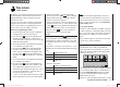
Important note:
When dealing with the interaction of multiple mixers
on one control channel, it is essential to remember
that the mixed travels of the individual mixers are
cumulative when multiple stick commands are made
simultaneously, and this brings a danger that the
servo concerned may strike its mechanical end-
stops. If you encounter this problem, simply reduce
the servo travel in the “Servo settings” menu, and /
or reduce the mixer values. However, if you do not
wish to reduce the travels in this way, because this
method would unnecessarily reduce the control
travels you normally use, then you may prefer an
alternative method of preventing the servos striking
their end-stops: set a suitable travel limit in the
“TRAVEL -/+” lines of the “RX SERVO” display page
of the “Telemetry” menu.
sides of centre, or have to offset the mixer neutral point,
then you should set or leave the pre-set mixers at “0”,
and program one of the free mixers instead.
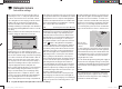
Erasing mixers
If you need to erase a mixer that you have already
defi ned, use the arrow buttons cd of the left or right-
hand four-way button to select its line, then use the
arrow buttons ef to move to the “from” column before
pressing the central SET button of the right-hand four-
w
ay button. The fi eld in the “from” column of the mixer to
be erased is now highlighted: simultaneously press the
two arrow buttons cd or ef of the right-hand four-
way button (CLEAR).
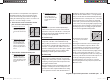
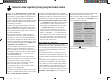
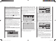
Mixer switches
In our example above, a physical switch “5” and the
control switch “C1” have been assigned to the two linear
mixers 1 and 2, and switch “3” to mixer 3.
The switch symbol to the right of the switch number
shows the current status of that switch.
Any mixer to which no switch has been assigned in
the column marked by the switch symbol
at the
bottom of the screen is permanently switched on.
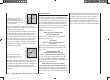
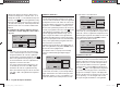
“Type” (including the trim)
If you wish, and if you are using one of the primary
control functions 1 … 4, you can set the trim value of
the digital trim lever for the associated stick to affect the
mixer input. This is accomplished by pressing the central
SET button of the right-hand four-way button, then using
its arro
w buttons to select “Tr” in the highlighted fi eld.
Note:
The effect of the Ch 1 trim lever on the mixer output var-
* NN = Nomen Nominandum (name to be stated)
33112_mx12_HoTT_2_GB.indd Abs36:10833112_mx12_HoTT_2_GB.indd Abs36:108 06.06.2011 19:39:4206.06.2011 19:39:42