
User's Manual

109
Program description: free mixers
Start by rotating the transmitter control to its left-hand
end-point, and adjust the landing fl ap linkages so that
they are in the neutral (retracted) position at this setting.
If you now turn the knob to the right, the fl aps should
defl ect down; if they move up, you must reverse the
direction of servo rotation.
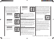
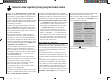
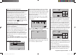
Now we turn to the fi rst mixer on the screen on page
107; this is the mixer “6 ¼ el”, to which switch 5 has
been assigned:
typ fro
to
M1
M2
M3
c1
el
c1
6
el
el
S
5
3
Press the central SET button of the right-hand four-way
b
utton to open the second screen page:
MIX1 6 el
off
If this display appears, you have not activated the mixer
b
y operating the assigned external switch - in this case
“5”. To correct this, operate the switch:
Mixer ratios and mixer neutral point
Now that we have explained the wide-ranging nature of
the mixer functions, we can move on to the method of
programming linear and non-linear mixer curves.
For each of the three available mixers the mixer curves
are programmed on a second page of the screen
display. Use the arrow buttons cd of the left or right-
hand four-way button to select the desired mixer line,
use its arrow buttons to move to the right-hand column
(=>), then press the central SET button of the right-hand
f
our-way button to switch to the graphic page.
Setting up linear mixer values
In the next section we will describe a typical practical
application, by defi ning a linear mixer curve intended to
solve the following problem:
We have a powered model with two fl ap servos con-
nected to receiver output 6 using a Y-lead. These control
surfaces are to be employed as landing fl aps, i. e. when
the associated transmitter control is operated, they
defl ect down only. However, this fl ap movement requires
an elevator trim correction to counteract the resultant
pitch trim change.
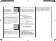
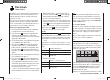
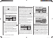
In the “Transmitter control settings” menu, assign the
rotary proportional control CTRL 7 (for example) to input
6.
“Transmitter control settings” menu
I5
I6
+
trv
ctrl 7
+100%
+100%
+100%
+100%
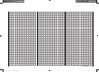
free
MIX1 6 el
trv
0%
0%
0%offs
ASYSYM
The full-height vertical line in the graph represents the
current position of the tr
ansmitter control assigned to
input 6. (In the above graph this is located at the left-
hand edge because CTRL 7 is at its left-hand end-point,
as already mentioned.) The full-length horizontal line
shows the mixer ratio, which currently has the value of
zero over the whole of stick travel; this means that the
elevator will not “follow” when the fl aps are operated.
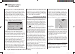
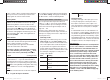
The fi rst step is to defi ne the offset (mixer neutral point).
To do this press the arrow button d of the left or right-
hand four-way button and move to the “Offs” line:
MIX1 6 el
trv
0%
0%
0%offs
SELSTO
The dotted vertical line indicates the position of the
mix
er neutral point (“offset”), i. e. that point along the
control travel at which the mixer has NO infl uence on the
channel connected to its output. By default this point is
set to the centre position.
However, in our example the neutral (retracted) posi-
tion of the fl aps is located at the left-hand end-stop of
the rotary proportional control, and in this position the
elevator must not be affected. We therefore have to
33112_mx12_HoTT_2_GB.indd Abs36:10933112_mx12_HoTT_2_GB.indd Abs36:109 06.06.2011 19:39:4206.06.2011 19:39:42