
User's Manual

119
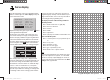
Program description: Telemetry menu
L.R-VOLT Lowest receiver operating voltage
since the last power-on, in Volt
SENSOR1 Shows the values of the optional
telemetry sensor 1 in Volt and °C
SENSOR2 Shows the values of the optional
telemetry sensor 2 in Volt and °C
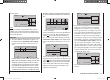
Signal quality (S-QUA)
The signal quality (S-QUA) is sent “live” to the transmit-
ter via the receiver’s downlink channel, and shows the
signal strength in %.
Receive performance (S-dBm)
The receive performance (S-dBm) is displayed as a
negative value, i. e. a value approaching zero is the
highest value (= best reception). The lower the value
falls, the worse is the receive performance. This is an
important item of information, particularly when you are
carrying out a range-check before operating the model.
Note:
In the case of negative numbers the value is reversed:
the higher the number following the minus sign, the
lower the value.
Carry out a range-check as described on pages 62 and
71 before every fl ight, and remember to simulate all the
servo movements which are likely to occur in the air.
In active range-check mode the range must be at least
fi fty metres on the ground. To guarantee safe operation
of your model, a value no higher than -80 dBm must be
displayed in the “RX DATA” display under “S-dBm” at this
distance. If the value falls below this (e. g. -85 dBm), you
should under no circumstances fl y your model. Instead
check the receiving system installation and the aerial
positions.
When operating a model this value should not fall below
-90 dBm; if it does, reduce the distance between the
pilot and the model. However, the audible range warn-
ing (beeping at one-second intervals) will normally be
triggered before this value is reached, in order to ensure
safe operation.
Signal strength (S-STR)
The value for signal strength (S-STR) is displayed in %.
An audible range warning (beeping at one-second inter-
vals) will always be generated as soon as the receiver
signal in the downlink channel is too weak. However,
since the transmitter has a much higher transmitting
power than the receiver, the model can still be operated
safely at this point. Nevertheless, in the interests of
safety the distance to the model should be reduced until
the audible warning ceases.
Receiver temperature (R-TEM.)
Ensure under all fl ight conditions that the receiver stays
within its specifi ed temperature range (ideally between
-10 and +55°C).
The limit values for receiver temperature after which
a warning occurs can be set in the “SERVO TEST”
sub-menu under “ALARM TEMP+” (50 … 80°C) and
“ALARM TEMP-” (-20 … +10°C). If the temperature
exceeds or falls below the set limit, an audible signal
(continuous beeping) is triggered, and “TEMP.E” is
displa
yed at top right in all the “RX” receiver sub-menus.
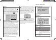
At the same time the “R-TEM“ parameter is highlighted
on the “RX DATAVIEW” screen page.
Data packets (L PACK TIME)
This displays the longest period in ms in which data
packets were lost in transmission from the transmitter to
the receiver. In practice this means the longest time in
which the radio control system went into Fail-Safe mode.
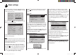
Operating voltage (R-VOLT)
Check the receiver’s operating voltage constantly. If it is
too low, you must under no circumstances continue to
operate your model, and certainly not launch it.
The low receiver voltage warning can be adjusted within
the range 3.0 to 6.0 Volt in the “SERVO TEST” sub-menu
under “ALARM VOLT”. If the voltage falls below the
threshold, an audible signal (repeated double beep, long
/ short) is generated, and in all the receiver sub-menus
“RX …” you will see “VOLT.E” at top right. At the same
time the par
ameter “R-VOLT” is highlighted in the “RX
DATAVIEW” sub-menu.
The current receiver battery voltage is also shown in the
basic display; see page 24.
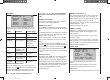
Minimum operating voltage (L.R-VOLT)
“L.R-VOLT” shows the receiver’s minimum operating
voltage since the last time it was switched on.
If this voltage differs signifi cantly from the current
operating voltage “R-VOLT”, this could mean that the
receiver battery is being overstressed by the servos,
causing collapses in battery voltage. If this should occur,
we recommend installing a higher-performance receiver
battery to ensure maximum operating safety.
Sensor 1 + 2
Shows the values of the optional telemetry sensor 1
and, if present, sensor 2 in Volt and °C. You will fi nd a
description of these sensors in the Appendix.
33112_mx12_HoTT_2_GB.indd Abs45:11933112_mx12_HoTT_2_GB.indd Abs45:119 06.06.2011 19:39:4306.06.2011 19:39:43