
User's Manual

122
Program description: Telemetry menu
If interference occurs, the corresponding servo
moves to the position displayed in the “POSITION”
line for the duration of the interference, after the “de-
lay time” set in the “DELAY” line.
HOLD•
If interference occurs, a servo set to “HOLD” main-
tains the position last assessed as correct for the du-
ration of the interference.
OFF•
If set to “OFF” when interference occurs, the receiv-
er continues to send the last correct control signals
(which it has stored) to the corresponding servo out-
put for the duration of the interference. This can be
imagined as the receiver switching the signal wire
“off”.
But CAUTION: if the control signal is absent, ana-
logue servos and many digital servos offer no resist-
ance to the forces acting on the control surfaces, with
the result that the model’s control surface positions
are more or less quickly lost.
F.S.Pos. (Fail-Safe position)
For each OUTPUT CH (receiver servo socket) activate
(highlight) the value fi eld by pressing the central SET
b
utton of the right-hand four-way button, then use the
arrow buttons of the right-hand four-way button in the
“F.S.POS.” line to set the servo position which the servo
is to take up in “FAIL-SAFE” mode if interference should
occur. The setting can be entered in increments of 10 µs.
Default setting: 1500 µs (servo centre)
Important note:
The “F.S.POS.” function is also signifi cant if the receiver
is switched on, but is (not yet) receiving a valid signal;
this applies to all three modes “OFF”, “HOLD” and “FAIL-
SAFE”:
The servo immediately runs to the Fail-Safe position pre-
viously set in the “Position” line. This can be exploited,
for example, to prevent the operation of a retractable un-
dercarriage or similar function if the receiver is switched
on accidentally. However, during normal model opera-
tions the corresponding servo behaves in accordance
with the set “MODE” if interference should strike.
DELAY (fail-safe response time or delay)
At this point you can set the delay time after which the
servos are to run to their previously selected positions if
the signal should be interrupted. This setting applies to
all channels, but only affects the servos programmed to
“FAIL-SAFE” mode.
Default setting: 0.75 s
FAIL SAFE ALL (global fail-safe setting)
This sub-menu can be used to defi ne the Fail-Safe
position of the servos simply by “pressing a button”; it
operates in a similar manner to the “Fail-Safe” menu
described on page 116, and is simple to use:
Move to the “FAIL-SAFE ALL” line and press the central
SET button of the right-hand four-way button to activate
the v
alue fi eld; “NO” is highlighted (black background).
Now set the parameter to “SAVE” using one of the ar-
row buttons of the right-hand four-way button. Use the
transmitter controls to move all the servos which you
have assigned - or intend to assign later - in the “MODE
- FAIL-SAFE” line, to the desired fail-safe positions. In
the extreme bottom line “Position” displays the current
position of the transmitter control for the channel you
have just set:
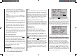
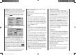
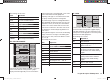
RX FAIL SAFE
INPUT CH: 01
MODE : FAI-SAFE
F.S.Pos. : 1500μsec
DELAY : 0.75sec
OUTPUT CH: 01
POSITION : 1670μsec
FAIL SAFE ALL: SAVE
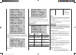
After pressing the central SET button of the right-hand
four-way button once more, the display reverts from
“SAVE” to “NO”. This indicates that the position of all the
servos affected by the procedure have now been stored,
and have also been adopted in the “F.S.Pos.” line. At
the same time the position for the current OUTPUT CH
(servo socket) is immediately displayed on the screen.
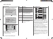
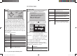
RX FAIL SAFE
INPUT CH: 01
MODE : FAI-SAFE
F.S.Pos. : 1670μsec
DELAY : 0.75sec
OUTPUT CH: 01
POSITION : 1670μsec
FAIL SAFE ALL: NO
Switch the transmitter off, and check the Fail-Safe posi-
tions by observing the servo movements.
“Fail-Safe” in combination with “channel mapping”
It is clearly desirable that mapped servos - i. e. servos
which are controlled by a common control channel
(INPUT CH) - should respond in the same way when
interference occurs, so the corresponding settings of the
INPUT CH determine the behaviour of mapped servos.
For example, if you are using a GR-16 eight-channel
receiver, Order No. 33508, and receiver servo sockets
6, 7 and 8 are mapped together, i. e. if the same control
channel “04” is assigned as INPUT CH to OUTPUT CH
(servo sockets) 06, 07 and 08 …
33112_mx12_HoTT_2_GB.indd Abs45:12233112_mx12_HoTT_2_GB.indd Abs45:122 06.06.2011 19:39:4306.06.2011 19:39:43